
How Does Aluminum MIG Wire Diameter Tolerance Matter
Article Directory
Welding aluminum is not as forgiving as welding steel. The material behaves differently under heat, reacts differently to feeding pressure, and requires a filler wire that maintains consistent performance throughout its length. For engineers and procurement teams involved in industrial fabrication, Aluminum MIG Wire Manufacturers are typically the primary contact when an issue arises in the welding process — or when results are satisfactory. The wire is not just a consumable. It is a process variable.
What Is Aluminum MIG Wire
The Basic Definition
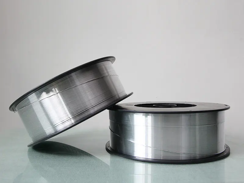
Aluminum MIG Wire is a solid, continuous filler material used in Metal Inert Gas welding to join aluminum and aluminum alloy components. During welding, the wire feeds through a gun at a set rate, melts into the weld pool alongside the base metal, and solidifies into a joint.
What separates aluminum wire from other filler materials is how the metal itself behaves. It has a lower melting point, conducts heat faster, and oxidizes on its surface almost immediately when exposed to air. The wire is also physically softer, which means feeding it through welding equipment requires more attention to tension, liner condition, and drive roll pressure than steel wire typically demands.
Industrial Applications
Aluminum MIG Wire shows up in fabrication environments that prioritize weight reduction, corrosion resistance, or both. Common sectors include:
- Automotive structural and body components
- Marine and shipbuilding assemblies
- Aerospace fabrication
- Industrial enclosures and equipment frames
- Transportation and trailer manufacturing
In each of these environments, the wire needs to produce repeatable results across long production runs — not just acceptable welds on individual pieces.
Alloy Families and Why They Matter
Not all Aluminum MIG Wire is the same alloy. The wire composition must be matched to the base material being welded and the performance requirements of the joint.
Two commonly used families are the 4xxx series, which contains silicon and is suitable for general fabrication and heat-treatable base alloys, and the 5xxx series, which contains magnesium and is often selected for marine and structural applications where corrosion resistance is prioritized. Choosing the wrong alloy family can affect weld strength, cracking tendency, and long-term performance — not just appearance.
What Is Diameter Tolerance in Wire Manufacturing
What the Term Actually Means
Every wire has a nominal diameter — the size it is meant to be. Diameter tolerance is the range of acceptable deviation from that nominal size along the wire's full length. It is not a single measurement taken once. It reflects how consistently the wire holds its cross-sectional size from one end of a spool to the other.
A tighter tolerance means less variation is permitted. A looser tolerance means the wire may fluctuate more widely, and equipment downstream has to deal with that inconsistency.
How the Drawing Process Introduces Variation
Aluminum MIG Wire starts as a rod that is pulled through a sequence of progressively smaller dies until it reaches its final diameter. The wire drawing process serves as a source of diameter variation.
Several factors contribute to fluctuation during drawing:
- Die wear, which gradually enlarges the bore over production cycles
- Variations in lubrication along the wire path
- Tension inconsistencies as spool weight changes during payoff
- Speed changes that affect how the metal flows through each die
- Temperature shifts in the material during extended production runs
None of these factors alone causes dramatic variation. But when several interact at once, the cumulative effect on diameter can push the wire toward the edge of its specification — or beyond it.
Tight Tolerance Is Always Relative
Whether a tolerance is considered tight depends on the wire's nominal diameter and the equipment it will run through. The same absolute deviation that is unremarkable in a larger wire may cause real problems in a smaller one, because the variation represents a larger proportion of the total wire size.
This scaling relationship is why tolerance specifications are typically written as plus-or-minus values, and why wire intended for precision applications carries tighter specifications than wire for general-purpose use.
Why Diameter Tolerance Affects Welding Performance
What Happens at the Feed System
The wire path from spool to arc runs through a liner, a set of drive rolls, and a contact tip. Each of these components is sized around the wire's nominal diameter. When the wire deviates significantly from that size, the fit changes — and so does behavior.
Sections that run thin may lose grip in the drive rolls, causing the feed rate to stutter. Sections that run thick create friction in the liner or resistance at the contact tip. Either condition introduces irregularity into the feed rate, and irregular feed rate is one of the primary sources of arc instability in MIG welding.
Electrical Transfer and Contact Tip Wear
The contact tip is where current moves from the equipment into the wire. The bore of the tip is sized to allow smooth wire passage while maintaining consistent electrical contact. When wire diameter varies:
- When the cross section is too small, the resulting loose fit can cause irregular current transfer and an unsteady arc.
- An oversized section drags through the tip, generating localized heat and accelerating wear
Contact tip replacement is a routine maintenance task, but in high-volume production, diameter-related tip wear can push that interval considerably shorter than expected — adding cost and downtime.
Arc Behavior and Weld Bead Outcome
Arc stability in MIG welding depends on a consistent relationship between feed rate, electrical input, and the physical properties of the wire at the point of melting. Diameter variation disrupts that relationship directly.
A cross-section that is larger than nominal carries more current and melts differently. One that is smaller does the opposite. These shifts alter the arc length, change heat input into the weld pool, and produce variation in bead width, height, and penetration. Over a full production run, that variation accumulates into measurable inconsistency in finished welds.
Quality Problems That Surface Downstream
The consequences of poor tolerance control are not always caught at the welding station. They often appear later:
- Porosity where shielding gas coverage broke down during arc fluctuation
- Burn-through on thin sections exposed to excess localized heat
- Incomplete fusion where an irregular arc failed to fully melt the base material
- Elevated rework rates and inspection failures that trace back to wire consistency, not operator error
Identifying these problems after the fact is significantly more expensive than specifying wire with appropriate tolerance control from the start.
How Manufacturers Keep Tolerance Under Control
Die Management
Die wear is predictable. Manufacturers who treat die replacement as a scheduled interval rather than a reactive repair reduce the risk of gradual diameter drift going undetected through a production run. The frequency of that interval depends on the alloy being drawn, the drawing speed, and the lubrication system in use.
Continuous In-Line Measurement
Laser-based diameter measurement systems installed along the drawing line allow manufacturers to monitor wire size in real time rather than sampling finished spools after production. When the wire approaches the edge of tolerance, the system flags the deviation immediately — giving the operator the opportunity to adjust before the wire moves out of specification.
Without in-line measurement, diameter variation can persist through an entire production batch before it is identified.
Speed, Tension, and Alloy-Specific Parameters
Drawing parameters that work for one alloy do not automatically transfer to another. Each alloy has its own deformation characteristics, work hardening rate, and surface behavior during drawing. Manufacturers working across multiple alloy families need separate process settings for each, validated against the tolerance requirements of the wire being produced.
Speed and tension management are particularly important. Changes in spool weight as material pays off can alter tension on the wire path. Inconsistent motor speed across drawing stages can introduce periodic variation that shows up as regular fluctuation in the finished wire diameter.
What to Consider When Evaluating Wire for Production Use
Before committing to a wire source for regular production use, the following factors are worth reviewing:
- Tolerance specification — whether the stated range matches the bore specifications of the contact tips and equipment being used
- Alloy documentation — whether the wire chemistry is certified against the base material requirements of the application
- Surface cleanliness — aluminum wire with residual oxidation or drawing lubricant on the surface introduces contamination into the weld pool
- Spool winding — uneven winding creates tension changes during payoff that interfere with feed rate consistency
- Traceability records — heat numbers, inspection data, and production documentation matter in regulated industries where weld quality must be auditable
Closing
Diameter tolerance is one of those specifications that tends to get overlooked until it causes a problem. By then, the cost is already in the rework pile, the scrap rate, or the accelerated maintenance schedule. Understanding the relationship between how Aluminum MIG Wire is made and how it performs in equipment gives procurement and engineering teams a more grounded basis for evaluating what they buy.
For teams sourcing aluminum welding consumables, Hangzhou Kunli Welding Materials Co., Ltd. produces Aluminum MIG Wire with controlled diameter tolerance designed to support consistent feeding and stable arc performance across industrial production environments. Reach out to discuss alloy options, tolerance specifications, or sample evaluation.
NEXT:How MIG Wire Cast and Helix Affect Weld Quality?


