
Quick Decision Guide For Wire Selection
Article Directory
- 1 Which alloys are commonly chosen for Aluminum Mig Wire
- 2 How does aluminum alloy welding wire affect welding performance
- 3 Why Aluminum Mig Wire matters to modern fabricators
- 4 How feeding systems change outcomes for aluminum welding
- 5 Practical setup checklist for a stable Aluminum Mig Wire process
- 6 Which spool types and diameters work for specific scenarios
- 7 How to match filler to base metal without overcomplicating procurement
- 8 Ways to control heat input and reduce distortion when welding aluminum
- 9 What common defects reveal about the process and how to diagnose them
- 10 How automation has adapted to Aluminum Mig Wire and why integration matters
- 11 How supply dynamics and recycling trends are shaping filler purchasing decisions
- 12 Which welding parameter strategies reduce rework on mixed-alloy assemblies
- 13 Tips for storage and handling to protect Aluminum Mig Wire integrity
- 14 Which industries are buying more aluminum filler and why
- 15 Ways to reduce feed interruptions that cause downtime
- 16 Which handling practices prevent surface contamination problems
- 17 Which environmental and safety practices protect staff during aluminum welding
- 18 Which finishing practices reduce visible weld repair time?
- 19 How to onboard aluminum filler into a multi-shift operation
- 20 Tips for preventing foreign material inclusion during welding
- 21 Why cooperative supplier relationships shrink qualification cycles
- 22 How repair workflows differ for thick sections compared with thin panels
- 23 Quick decision guide for wire selection and feeding method
- 24 Which inspection checkpoints reduce leaks and functional failures in welded assemblies
- 25 Ways to scale a pilot line to full production while maintaining weld quality
- 26 How to keep feed systems consistent across machines
- 27 Typical troubleshooting checklist for weld technicians
- 28 How to set up a repeatable maintenance plan for feeder systems
- 29 Simple on-floor checklist for shift start
- 30 How to reduce the hidden cost of frequent spool swaps
- 31 Ways to test a new spacer or backer material before committing to a process change
- 32 How to convert a successful prototype weld into a repeatable production operation
- 33 How to monitor for subtle degradation in weld quality over long production runs
- 34 How to keep a reserve of proven consumables without overstocking
On modern shop floors, small choices about wire form and feeder setup shape production rhythm, quality, and finishing time. When procurement, process engineering, and maintenance teams evaluate consumables, Aluminum Mig Wire Manufacturers offer a range of alloy options, spool formats, and handling guidance that determine how smoothly a project moves from prototype to steady production. Practical trials and cooperative sample programs narrow uncertainty before a lot reaches the line, and suppliers that provide clear handling notes and spool traceability reduce qualification time for welding teams. kunliwelding. partners with customers to supply sample spools, feeder recommendations, and on-floor support so engineering groups can validate parameters under real handling conditions and limit avoidable rework.
Which alloys are commonly chosen for Aluminum Mig Wire
When fabricators select Aluminum Mig Wire, several alloys appear more frequently because they match a wide range of base metals and production needs. The following options are widely used in workshops, production lines, and automated welding cells:
| Alloy | Key Elements | Typical Use Case |
|---|---|---|
| 4043 | Silicon | General fabrication, cast aluminum |
| 5356 | Magnesium | Structural parts, marine components |
| 5183 | Magnesium | Toughness-focused assemblies |
| 5556 | Magnesium | Strength-critical applications |
| 4047 | Silicon | Thin joints, reduced cracking needs |
How does aluminum alloy welding wire affect welding performance
Choosing the right aluminum wire alloy is a practical tradeoff between weld pool behavior, post-weld properties, and compatibility with the base metal. Wires with higher silicon content can flow well and mask minor fit-up gaps, while magnesium-bearing wires can improve strength in certain wrought alloys. For customers, the conversation with a supplier should focus on what the finished component needs rather than catalog labels alone. Practical trial welds and clear acceptance criteria save time and clarify whether a given wire chemistry fits a specific production requirement.
Why Aluminum Mig Wire matters to modern fabricators
Aluminum filler metal is becoming more visible on production floors where weight reduction and corrosion performance are priorities. Fabricators find that when wire chemistry, spool handling, and equipment setup match the job, aluminum welding productivity rises and rework falls. Recent shifts in material sourcing and recycling priorities are nudging purchasing teams to rethink how they specify filler metal and how they test incoming reels.
How feeding systems change outcomes for aluminum welding
Aluminum wire is softer than many other filler metals and responds to handling differently. Long feed paths, worn liners, or excessive back tension create snags, birdnests, and erratic arcs. Many fabricators move away from a pure push approach and use spool-on-gun or push-pull systems to smooth delivery. Attention to contact tip type, liner condition, and spool tension avoids many interruptions on the line. Manufacturers that standardize these hardware choices report fewer setup delays and clearer data when diagnosing welding issues.
Practical setup checklist for a stable Aluminum Mig Wire process
- Confirm wire alloy and diameter match the application
- Inspect spool for proper winding and contamination before mounting
- Use a smooth-diameter liner designed for aluminum and replace liners on a predictable schedule
- Choose an appropriate feeding method (spool gun, push-pull, or spool-on-gun) based on cable length and robot or manual setup
- Maintain consistent spool tension and clean contact tips regularly
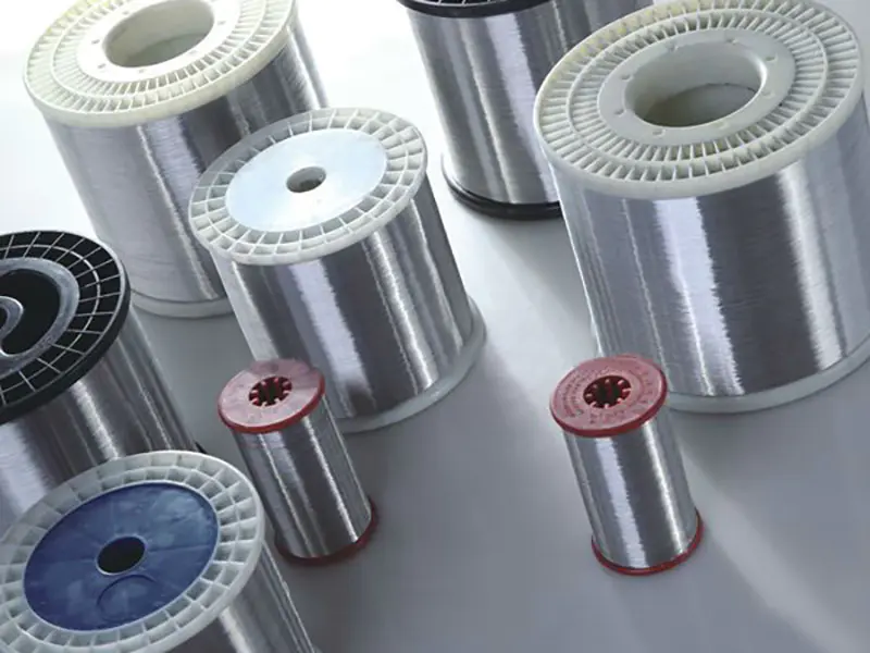
Which spool types and diameters work for specific scenarios
| Production goal | Typical spool form | Notes for handling |
|---|---|---|
| Short-run repairs or field service | Small spool mounted on spool gun | Keeps feeder path short; helps portability |
| High-volume robotic line | Large drum or boxed spool with managed payout | Use guided pay-off, avoid long free spans |
| Bench welding and prototypes | Medium spool on traditional feeder | Replace liners more often if feed path is coiled |
How to match filler to base metal without overcomplicating procurement
Fabricators should avoid choosing wire solely by catalogue name. Instead, specify: base alloy family, desired mechanical characteristic (toughness, ductility), and any post-weld finish expectations. When a supplier such as kunliwelding. receives clear requirements, sample packs and weld coupons can be produced quickly so engineering can qualify the consumable under actual process conditions.
Ways to control heat input and reduce distortion when welding aluminum
Aluminum responds to heat differently from many other metals. Its high thermal conductivity and relatively low melting range make distortion a common challenge during fabrication. Controlling heat input is essential to protect dimensional accuracy and reduce post-weld correction work. The following techniques help maintain stable weld geometry and lower the risk of warping across both manual and automated setups.
- Use faster travel speeds to limit puddle expansion
Keeping the torch moving at a steady, brisk pace prevents overheating zones near the joint. Faster travel creates a narrower heat band and helps reduce the stretching that leads to distortion. This technique works especially well on long seams and thin-wall components.
- Select lower-amperage starting points and adjust gradually
Beginning with lower amperage and checking puddle behavior before increasing power ensures that heat does not spike early in the weld. Gradual tuning helps keep the joint temperature balanced and reduces the sudden softening that typically causes part movement.
- Apply pulse settings to stabilize the arc
Pulse modes create controlled bursts of energy that allow the weld to penetrate without saturating surrounding material with continuous heat. This keeps the workpiece cooler overall and is useful when welding thin sheets, complex assemblies, or panels that could shift under prolonged heat.
- Use appropriate joint fit-up to avoid overfilling
Tight joints require less filler metal and therefore lower heat. Ensuring consistent fit-up minimizes large gaps that would otherwise require excessive Aluminum Mig Wire feed and additional heat input to bridge them. Good dimension control reduces distortion risk significantly.
- Clamp assemblies securely and distribute restraint points
Clamping keeps parts from pulling or rotating during heating. Using multiple, evenly spaced restraints helps spread thermal stress so that no single area absorbs too much expansion. This method also improves alignment throughout the weld.
- Pre-tack the assembly to lock geometry
Tack welds placed at strategic intervals hold panels or profiles in the correct shape. These tacks limit movement as the main weld progresses. Small, evenly spaced tacks help keep distortion predictable and easier to manage.
- Use backstep or skip welding sequences
Short welds applied in alternating directions break up heat concentration. Backstep patterns introduce heat in a staggered manner, while skip welding spreads the process across multiple sections before returning to fill gaps. Both strategies allow cooling time between passes.
- Keep interpass temperature stable
When working on multi-pass joints, letting the material cool between passes helps maintain consistent expansion. Monitoring interpass temperature reduces overheating and preserves joint shape.
- Select thicker backing bars or copper fixtures
Copper backing conducts heat away quickly, helping keep aluminum panels cool. Durable backing bars stabilize thin sections, reduce burn-through risk, and diminish local expansion. This approach is effective for sheet-metal production and long seam assemblies.
- Minimize dwell time at arc starts and stops
Holding the arc too long at the beginning or end of a weld adds unnecessary heat and often creates distortion near edges. Smooth starts and controlled ramp-out settings reduce local stress and improve overall flatness.
What common defects reveal about the process and how to diagnose them
When porosity appears, the likely suspects are surface contamination, trapped moisture, or improper shielding gas coverage. Lack of fusion often traces to insufficient heat input or an incorrect travel angle. Wire feeding hiccups usually point toward the mechanical path: spool condition, liner wear, or mismatched contact components. A simple diagnostic table helps technicians isolate causes quickly.
| Symptom | Initial inspection point | Quick corrective action |
|---|---|---|
| Erratic arc or birdnesting | Wire spool path and liner | Replace liner, check spool tension |
| Porosity in beads | Part cleanliness and gas flow | Clean parts, verify gas nozzle and flow |
| Excessive warpage | Heat input and weld sequence | Reduce heat per pass, add clamps |
How automation has adapted to Aluminum Mig Wire and why integration matters
Automated welding cells have been adjusted to accommodate softer aluminum wire by shortening feed paths, using water-cooled torches on high-duty cycles, and employing controlled payout systems. Robotic integrators and welding engineers coordinate to reduce free loops and to specify end-of-arm tooling that preserves wire condition. When engineering teams allocate time for wire management early in integration, run yield improves and troubleshooting cycles shrink.
How supply dynamics and recycling trends are shaping filler purchasing decisions
Global attention on circular material flows and competition for high-quality scrap is changing how buyers source aluminum feedstock across the value chain. Sourcing strategies increasingly include validated recycling streams or contractual arrangements to stabilize supply for critical alloys.
Welding mixed-alloy assemblies introduces challenges that do not appear in single-alloy structures. Differences in thermal conductivity, melting behavior, joint rigidity, and surface condition can trigger distortion, inconsistent penetration, and fusion issues. Each of these can push defect rates upward if parameters are not tuned carefully. The following strategies help stabilize the process and keep rework under control.
Which welding parameter strategies reduce rework on mixed-alloy assemblies
1. Tune heat input to the slower-responding alloy
Mixed-alloy joints often pair alloys that absorb or release heat differently. Adjusting voltage and wire-feed settings according to the alloy with slower thermal response minimizes overheated edges and incomplete fusion. Maintaining a controlled heat window prevents undercut on softer alloys and excessive melt-off on higher-conductivity alloys.
2. Match travel speed to joint balance
Travel speed that suits one alloy may be too fast or too slow for the other. In combination joints, selecting a moderate travel speed gives both alloys time to reach workable puddle behavior without overheating one side. This practice improves bead consistency and lowers the chance of cold-lapped zones.
3. Use waveform settings that stabilize arc transfer
Modern MIG equipment allows waveform adjustments that help equalize puddle behavior across mixed materials. Settings that create smoother droplet transfer help control spatter and improve blending at the alloy interface. A stable waveform creates a more predictable weld pool even when one alloy melts earlier than the other.
4. Adjust stickout to improve joint access and puddle shape
Slightly shorter stickout supports a more concentrated arc, which helps manage joint areas where alloys meet at different melt points. This reduces the chance of arc wandering, which is common when one alloy surface reflects heat differently from the other. A consistent puddle minimizes edge-notches that would otherwise require grinding and rework.
5. Balance shielding coverage for mixed-surface behavior
Some alloys outgas more or hold more surface oxides. Increasing shielding-gas flow slightly or optimizing gas nozzle angle can prevent turbulence and protect the puddle uniformly. Even gas coverage helps avoid porous areas that often occur where the two alloys transition.
6. Use ramp-in and ramp-out settings to control bead tie-in
Mixed-alloy joints frequently suffer from inconsistent tie-in at the start and stop points. Smoother ramp-in and ramp-out settings provide gentler puddle formation and contraction, which reduces crater issues. Good control at both ends of the bead cuts down on small repairs that accumulate into significant rework time.
7. Fine-tune wire-feed speed for multi-alloy edges
Wire-feed speed directly impacts puddle size and arc stability. When joining alloys with different melting characteristics, adjusting wire-feed speed to match the part of the joint that cools quicker helps maintain uniform bead height and penetration. Balanced feed reduces excessive filler buildup on one side and underfill on the other.
8. Use preflow and postflow timing to protect heat-sensitive alloys
Alloys that oxidize quickly benefit from extra shielding before and after the arc extinguishes. Preflow helps avoid instant surface oxidation as the arc starts, while postflow protects the solidifying puddle. These parameters reduce the risk of surface contamination that often appears as cosmetic or functional defects.
9. Keep interpass temperature steady across both alloys
Temperature swings are more noticeable in mixed-alloy assemblies because one side may hold heat longer than the other. Monitoring interpass temperature and pausing to let the hotter alloy stabilize prevents distortion and uneven fusion. Consistent interpass control improves bead uniformity and lowers the need for straightening work later.
10. Apply pulsed parameters when heat sensitivity varies sharply
Pulse settings help keep average heat low while providing controlled energy bursts for good penetration. This helps welders avoid burn-through on thin or heat-sensitive alloys while still getting a continuous bond across the harder-to-melt alloy. Pulse tuning reduces defects that typically emerge in transition zones between dissimilar materials.
Tips for storage and handling to protect Aluminum Mig Wire integrity
Wire performance begins before it reaches the torch. Keep spools in a controlled environment away from chemical vapors and excessive humidity. Use sealed packaging until ready to load and clean exterior spool surfaces before mounting. For high-volume production lines, manage stored spools using first-in, first-out practices and maintain lot number records to facilitate root cause analysis if issues occur.
Which industries are buying more aluminum filler and why
Industries with growing demand for aluminum filler & main drivers
1. Automotive (including EVs and light-vehicle manufacturing)
- The automotive sector accounts for a major share of welded aluminum components demand, especially as lightweight materials become more important for fuel efficiency and electric-vehicle (EV) range.
- As automakers increasingly adopt aluminum for chassis, battery enclosures, body panels and structural parts, the need for reliable aluminum welding filler rises accordingly.
- Trend toward lighter, corrosion-resistant, and recyclable materials makes aluminum a preferred choice, driving demand for aluminum filler wires.
2. Aerospace and Defense
- Aerospace applications demand materials with good strength-to-weight ratio and corrosion resistance; aluminum welding filler meets those needs, so aerospace manufacturing drives filler demand.
- As aircraft and related components often require precise, high-quality welds — including MIG or other processes using aluminum wire — the aerospace sector remains a stable major consumer of aluminum filler.
3. Shipbuilding / Marine & Offshore / Marine-industry fabrication
- Marine and shipbuilding industries rely on aluminum for corrosion-resistant and lightweight structures; aluminum welding filler supports those builds. Market reports for welding wire suppliers show high demand from shipbuilding and marine sectors.
- Offshore structures and marine-grade assemblies often use aluminum alloys that weld well with filler wire — a stable base for filler-wire demand when marine construction or repair increases.
4. Appliance, HVAC, and Electrical Industry
Aluminum is widely used in electrical enclosures, heat-exchange units, HVAC frames, and housings where conductivity, corrosion resistance, and light weight matter — boosting filler demand for welding these products.
As consumer demand grows and manufacturing scales, more aluminum structures and casings are produced, increasing consumption of aluminum welding consumables.
5. Construction, Infrastructure, and Modular Fabrication
- Infrastructure projects, modular building components, and lightweight structural assemblies increasingly favor aluminum for durability and reduced weight compared with heavier metals.
- As global construction and infrastructure investment continues, demand rises for pre-fabricated aluminum modules — many joined via welding — generating consistent demand for aluminum filler.
6. Renewable Energy & Green Infrastructure (e.g. Solar, Wind, EV Infrastructure)
- Growth in renewable energy installations, electric vehicle infrastructure, and lightweight structural components supports the use of aluminum for its corrosion resistance and recyclability.
- As companies push for sustainable materials, aluminum welding becomes more common — fueling demand for aluminum filler wires designed for modern energy-sector applications.
Reasons Driving the Shift Toward Aluminum Filler
- Lightweight and Corrosion Resistance Needs: In automotive, aerospace, marine, and renewable energy — weight reduction and resistance to corrosion or environmental exposure make aluminum highly attractive. Welding filler wires support joining these aluminum parts reliably.
- Regulatory and Environmental Pressure: Emission regulations, fuel-efficiency targets, and sustainability goals push manufacturers to adopt lighter materials; aluminum welding consumables benefit from this shift.
- Growth in Electric Vehicles and Infrastructure: As EV production grows, so does demand for aluminum-based battery enclosures, frames, and lightweight assemblies — all needing filler metal for welding.
- Increased Use of Prefabricated Aluminum Modules: For large-scale manufacturing, modular construction, and standardized assemblies, aluminum welding enables scalable production — encouraging more filler usage.
- Industrial Trend Toward Automation and High-Volume Welding: As factories adopt robotics and automated welding lines, demand for consistent, high-quality aluminum welding wire rises — which benefits suppliers and manufacturers alike.
Ways to reduce feed interruptions that cause downtime
Feed interruptions can stop production, disrupt welder rhythm, and introduce quality inconsistencies. When using Aluminum Mig Wire, smooth feeding depends on consistent tension, clean pathways, and predictable handling routines. The following methods help limit unplanned pauses and keep weld flow steady across long shifts.
- Keep liners clean and replace them before wear becomes visible
Aluminum shavings and dust gradually build inside liners, increasing drag on the wire. Even slight resistance can create pauses that escalate into full feed stoppages. Replacing liners on a predictable cycle, rather than waiting for visible damage, keeps wire travel smooth and reduces sudden slowdowns.
- Match drive roll type and tension to the wire
Incorrect drive roll pressure can deform soft aluminum wire or allow slipping when the feeder encounters slight resistance. Using rolls suited to aluminum profiles and adjusting tension just enough to grip the wire without flattening it keeps feeding stable. A quick check at each shift change prevents cumulative drift.
- Confirm spool orientation and drag consistency
If a spool rotates unevenly or experiences unpredictable drag, the feeder may momentarily stall. Ensure each spool sits squarely in its holder with smooth rotation and predictable resistance. Removing excess tape or trimming tangled outer layers helps the wire unwind smoothly.
- Reduce sharp bends and friction points in the cable
Aluminum wire bends easily under pressure, and sharp curves increase friction. Position feeders and torches to maintain broad, shallow cable arcs. Organize hoses and cables to avoid pinching or looping that restricts movement during welding.
- Use clean, dry storage to protect spools
Moisture or airborne shop debris can stick to the wire and create small friction points inside the liner. Keeping spools capped or stored in clean containers until installation reduces foreign material buildup and improves long-term feed stability.
- Inspect contact tips for early signs of wear
Contact tip wear gradually changes the wire's exit behavior, increasing drag and arc instability. Checking tips during breaks or planned spool changes prevents feeding inconsistencies that appear as brief stops or sudden hesitations.
- Keep feeders free from dust and residue
Dust around drive rolls, gears, or internal pathways can accumulate and interfere with rotation. A quick daily cleaning routine, especially in high-traffic welding areas, helps maintain smooth wire delivery throughout the shift.
- Train operators in controlled wire trimming
If the wire tail is cut unevenly or left with a hook, it may snag inside the liner or drive roll. Teaching operators to trim the wire cleanly before every spool load reduces small but frequent feed issues that interrupt work.
- Check torch angle habits during long weld passes
Excessive torch tilt can cause drag where the wire enters the contact tip. Encouraging a steady angle during flat, vertical, and overhead positions helps keep the wire flowing without friction-induced delays.
- Track interruptions to identify station-specific patterns
Some workstations experience more feed problems due to layout, airflow, cable routing, or operator routines. Keeping a simple log of interruptions helps teams identify and fix repeating issues that would otherwise remain hidden.
Which handling practices prevent surface contamination problems
Surface contamination is a frequent cause of weld inconsistency, particularly when working with aluminum components and aluminum MIG wire. Because aluminum readily attracts oxides, oils, and airborne residue, handling practices play a direct role in maintaining clean surfaces that support stable arc behavior, smooth bead formation, and predictable fusion. The following techniques help reduce contamination risks across everyday production workflows.
- Use clean gloves when touching aluminum parts
Skin oils transfer easily onto aluminum and can spread across the joint line. Wearing clean gloves reserved only for aluminum handling reduces the chance of oil marks that later burn into the weld pool. Replace gloves if they accumulate dust, dirt, or coolant residue.
- Keep parts off bare workbenches
Workbenches often carry metal chips, grinder dust, cutting oils, and general shop debris. Using dedicated pads, clean trays, or non-metallic mats keeps parts from picking up contaminants that might become trapped inside the weld zone during heating.
- Store components in covered containers or shelving
Open shelving exposes aluminum surfaces to airborne particles from machining, grinding, and traffic areas. Covered bins or enclosed shelves shield parts from dust and stray chips, reducing extra cleaning time before welding.
- Separate aluminum tools from steel tools
Tools used on steel often carry embedded particles that can transfer onto aluminum surfaces. Keeping aluminum-only brushes, clamps, and handheld tools prevents cross-contamination and avoids foreign particles that might disrupt puddle flow.
- Avoid leaning parts against abrasive wheels or rough surfaces
Even brief contact with dirty surfaces can leave grit or fibers that later melt into the weld. Dedicated stands or coated racks help maintain clean contact surfaces and prevent accidental contamination during staging.
- Check for coolant, lubricant, or marking residue after machining
Machined aluminum frequently retains thin films of coolant or writing markers. Wiping parts promptly after machining and using suitable cleaners removes residue before it hardens or spreads across edges during handling.
- Keep spools and consumables sealed until loading
Aluminum Mig Wire exposed to dust or moisture during handling can carry contamination directly into the feeder or contact tip. Keeping spools in clean, sealed containers until installation helps maintain wire cleanliness throughout long runs.
- Use clean, soft barriers when stacking thin panels
Stacking thin aluminum sheets or panels without protective layers can trap abrasive dust or allow surfaces to rub against each other. Using clean separators reduces scratches, embedded particles, and oxide buildup.
- Inspect lifting straps, slings, and hooks
Handling gear can accumulate dirt, metal fragments, or chemical residue. Inspecting lifting equipment before contact with aluminum surfaces reduces the chance of transferring unwanted material onto the part during movement.
- Keep work zones organized to limit accidental contact
Crowded or cluttered areas increase the risk of bumping parts into grinders, cutting tools, or dirty surfaces. A well-organized environment limits incidental contact that leads to surface buildup and reduces last-minute cleaning tasks.
Which environmental and safety practices protect staff during aluminum welding
Aluminum welding presents unique environmental and safety considerations due to bright arc intensity, fine particulate release, and the need for stable work conditions. When operators handle Aluminum Mig Wire, the right practices help protect visibility, breathing comfort, and workspace stability while supporting consistent weld quality.
- Maintain clear airflow without disrupting shielding gas
Aluminum welding produces fine particles that can accumulate in enclosed areas. Use local extraction positioned to pull fumes away from the breathing zone while keeping the shielding gas pattern undisturbed. Balanced airflow helps maintain puddle stability while improving operator comfort.
- Provide adequate eye protection for high arc brightness
Aluminum produces strong reflectivity, increasing glare compared with many other metals. Helmets with suitable filters and side protection reduce strain and help maintain visibility during long welding sessions. Additional glare shields can support operators working near reflective surfaces.
Keep the workspace dry and free from slip hazards
Condensation and coolant drips can collect around workstations. Placing absorbent pads under fixtures, organizing hoses, and keeping walkways dry reduces fall risks and prevents unexpected movement when operators reposition during welds.
- Control overhead lighting to reduce visual fatigue
Harsh or poorly placed lighting can interfere with the operator's view of the puddle. Adjustable lights positioned behind the welder or above the joint area improve clarity without introducing distracting reflections on aluminum surfaces.
- Ensure proper glove and clothing choices
Welding aluminum often involves varied heat flow. Operators benefit from gloves that allow dexterity while providing insulation from radiant and reflected heat. Clothing should be free of loose fibers to avoid airborne contamination and accidental contact with the arc.
- Use grounding and cable management to avoid trip risks
Cables running across walkways cause both tripping hazards and possible strain on feeders. Organizing cables along walls or under protective covers keeps movement smooth and reduces accidental tension during long weld runs.
- Verify that workpiece temperatures remain manageable
Aluminum can retain heat unpredictably during extended runs. Using infrared checks or simple touch-free tests helps operators avoid unexpected burns when repositioning workpieces. Spacing out weld sequences also supports manageable temperatures.
- Keep combustibles clear of hot surfaces
Aluminum spatter is typically low, but fixtures, rags, and packaging materials near the work zone can still heat up. Storing solvents, wipes, and packing foam away from the arc reduces the chance of accidental ignition during or after welding.
- Implement clear communication signals around active weld zones
Bright arcs and equipment noise limit verbal communication. Simple hand signals or light indicators let nearby staff know when a weld is active, when adjustments are needed, or when it is safe to approach. This prevents accidental exposure to the arc.
- Train staff in safe handling of Aluminum Mig Wire
Wire ends can spring unexpectedly when tension is released. Showing operators how to control the tail, check spool direction, and handle sharp wire edges protects hands and prevents accidental whipping during installation.
Which finishing practices reduce visible weld repair time?
Reducing visible weld repair time starts with small routine habits that limit excess cleanup and prevent rework from accumulating. When Aluminum Mig Wire is used in production settings, finishing becomes much easier when the weld surface is already clean, consistent, and accessible. The following practices help shrink the time spent on grinding, blending, and correcting surface flaws.
- Keep joint edges clean before welding
Surface contamination is one of the biggest causes of visible repair work. A simple wipe with an approved cleaner, followed by a light mechanical prep on oxidized edges, reduces soot, discoloration, and uneven surfaces that take extra time to smooth later.
- Maintain a stable wire feed path
A smooth, consistent arc produces a uniform bead that requires less blending. Regular checks of liners, drive rolls, and contact tips help reduce minor hitches that create small lumps or chatter marks. A uniform bead shape shortens final grinding time because fewer contours need adjustment.
- Use controlled travel speed to avoid overbuilding
Thick reinforcement takes longer to finish. Training operators to hold a stable pace prevents beads from becoming bulky. When the bead height stays consistent, finishing teams can move directly to light smoothing instead of deep grinding.
- Protect the weld from stray airflow
Inconsistent gas coverage can create small pores or surface roughness that must be repaired. Setting shields or repositioning the torch angle to improve coverage reduces the need for cosmetic patching once the weld cools.
- Implement a light brushing step during cooling
A quick brushing pass can remove loose residue before it hardens. This reduces the amount of compacted buildup that grinding crews must remove later. It also helps reveal early surface issues while they are easy to correct.
- Choose abrasives suited to aluminum finishing
Aluminum requires tools that resist loading. Using the right flap wheels, discs, or brushes keeps tools from smearing material across the surface. Clean, consistent cuts reduce time spent reopening clogged abrasives or correcting accidental gouges.
- Match weld placement to accessible angles
When possible, plan welds where finishing tools can reach easily. Tight corners or deep pockets slow down any repair or cosmetic pass. Adjusting fixture orientation or part layout often reduces hidden hours spent reaching awkward welds.
- Track which weld parameters reduce extra blending
Shops often find that small parameter shifts—such as slight adjustments to wire feed or torch angle—produce a bead that needs little more than a smoothing step. Recording these findings builds a library that helps operators repeat efficient settings.
- Keep finishing tools maintained and organized
Worn discs, contaminated brushes, or missing grits delay finishing. A simple tool board near the workstation ensures that operators can switch abrasives quickly and stay consistent from one part to the next.
How to onboard aluminum filler into a multi-shift operation
Standardize spool mounting, feeder procedures, and liner replacement intervals across shifts. Use checklists for shift handovers to prevent drift in setup and encourage operators to report any feed irregularities promptly so that maintenance can intervene before a production stop.
Tips for preventing foreign material inclusion during welding
Foreign material inclusion often starts with small contaminants that enter the weld zone without being noticed. When Aluminum Mig Wire is part of the process, the arc can trap debris, oxide particles, or residue inside the molten pool, creating weak spots or visible surface flaws. Keeping the weld area clean through simple, repeatable habits protects both structural and cosmetic quality.
- Clean the joint surfaces immediately before welding
Dust, oxide buildup, machining chips, and shop residue can settle quickly on aluminum. Preparing the surface right before welding—using suitable wipes or mechanical cleaning—ensures particles do not migrate into the weld pool moments later.
- Use dedicated brushes and tools for aluminum
Shared tools often carry steel particles, abrasive grit, or oil. Dedicated tools prevent cross-contamination and reduce the chance that stray fragments become embedded in the welding zone. Store these tools in a clearly identified area to keep them separated from general-use equipment.
- Protect open joints from airflow and foot traffic
Drafts can blow debris into exposed grooves, especially when parts sit in fixtures for long periods. Position wind shields or simple barriers around critical joints. Also avoid staging parts in walkways where airborne dust and chips are frequently kicked up.
- Keep consumables covered until installation
Spools, tips, and nozzles left unprotected can collect dust or workshop residue. Keep them sealed in clean containers until needed, and cap partially used spools when not in use. Even small particles sticking to the wire can enter the puddle during feeding.
- Inspect gloves, sleeves, and aprons for loose fibers
Textile fibers sometimes fall into the weld area when worn protective gear begins to fray. Checking for loose threads or embedding sleeves under arm guards reduces the risk of fibers drifting into the puddle when repositioning the torch.
- Maintain a clean liner and feed path
Aluminum wire can pick up dust or shaving fragments inside the liner. Regularly replacing liners and wiping the wire path helps prevent material deposits from breaking loose mid-weld. Smooth feeding reduces the chance of small contaminants entering the arc.
- Limit grinding near the welding zone
Particles from grinders or cut-off wheels can land inside an open joint. When the arc ignites, these particles may dissolve into the weld pool. Completing heavy grinding steps before final fit-up keeps debris away from sensitive surfaces.
- Use clean backers or spacers
Any backer used during welding should be free of residue, machining coolant, or embedded particles. Before setup, run a quick wipe and visual check to confirm that nothing can transfer into the weld root once the arc begins.
- Verify filler wire condition during spool changes
When changing spools, inspect the initial wraps of aluminum MIG wire for indicators such as dust, fine metallic particles, or discoloration. Trim past questionable layers so only clean wire enters the feeder.
- Store workpieces away from machining operations
Machining centers release fine chips that can settle on aluminum surfaces. Position welding fixtures away from these areas or install simple curtains that block airborne debris. Clean storage keeps parts free from material that could later become trapped in the weld.
Why cooperative supplier relationships shrink qualification cycles
Open communication about expected application conditions, willingness to supply sample spools, and responsive troubleshooting shorten approval time. Suppliers that can document consistent spool quality and provide on-floor support reduce the friction of switching consumables.
How repair workflows differ for thick sections compared with thin panels
Repairing welded assemblies requires different approaches depending on whether the material is a heavy section or a thin panel. Each behaves differently under heat, distortion, and mechanical stress, especially when using Aluminum Mig Wire as the repair consumable. Understanding how these workflows diverge helps teams restore components efficiently while protecting structural integrity.
| Aspect | Thick Sections | Thin Panels |
|---|---|---|
| Heat Management | Absorb and retain heat longer; slower cooling affects puddle control | React quickly to heat; risk of warping requires short stitches and faster travel |
| Preparation | Requires deeper excavation to remove cracks | Uses shallow cleaning to avoid over-thinning |
| Fixturing | Generally stable with simple clamps | Needs supportive fixtures to limit flexing and distortion |
| Filler Use | Larger filler volume; often multiple passes | Minimal filler to limit heat and reduce post-work dressing |
| Cooling Approach | Slow cooling; checks for residual stress | Fast cooling; alternating sides helps limit pull |
| Defect Visibility | Focus on structural recovery | Requires closer cosmetic checks |
| Tool Choice | Allows heavier grinding and shaping tools | Needs lighter abrasives and low pressure |
| Operator Pacing | Steady pace, allowing heat to settle | Quicker passes with controlled timing to avoid overheating |
Quick decision guide for wire selection and feeding method
| Application type | Common wire diameter range | Recommended feeding approach |
|---|---|---|
| Thin cosmetic panels | Smaller diameters | Spool gun or close payout |
| Structural welds | Medium diameters | Push-pull with short liner |
| Robotic high-cycle lines | Medium to larger diameters | Spool-on-gun with guided payout |
Which inspection checkpoints reduce leaks and functional failures in welded assemblies
Leak prevention and functional reliability depend on structured checkpoints that catch small variations before they affect the final assembly. When working with processes that rely on Aluminum Mig Wire, consistent verification points help ensure each joint maintains stable fusion, dimensional accuracy, and long-term durability. The following checkpoints strengthen control over assemblies that must remain sealed, pressure-tight, or structurally consistent.
- Joint preparation and fit-up verification
Before welding begins, verify that edges are clean, free of oxides, and properly aligned. Even small gaps can create weak points where gas or fluid can later escape. Confirm that the joint design matches the intended specification and that spacers, clamps, and fixtures hold the parts securely.
- Root pass confirmation for assemblies with enclosed cavities
Check the initial weld pass at the earliest opportunity. Verify proper fusion, uniform wetting into corners, and a regular underside profile where accessible. Irregularities in the root often become hidden behind later passes, making this checkpoint one of the earliest opportunities to prevent internal leaks.
- Heat control and interpass behavior checks
Monitor how the joint responds to heat as the weld progresses. If the puddle becomes sluggish or overly fluid, small voids or incomplete transitions may form. Confirm that interpass temperature stays within the shop's usual range so that material behavior remains predictable.
- Gas coverage consistency review
Observe the shielding gas pattern near critical joints. Drafts, torch angle shifts, or blocked nozzles may introduce porosity that later leads to leaks. A quick flow check before starting every major weld line reduces these risks.
- Surface continuity and bead contour inspection
After the weld cools, examine the surface for undercut, uneven reinforcement, small pinholes, or ripple disruptions. These cues often indicate internal porosity or trapped pockets that weaken the joint or compromise sealing capability.
- Cross-section or cutout sampling for high-priority components
When possible, remove small sample coupons at controlled intervals. Cutting and examining these cross-sections reveals whether fusion depth, penetration uniformity, and joint transitions remain consistent. This method is useful for line validation or whenever long production runs introduce gradual drift.
- Dimensional and alignment verification
Misalignment can create tension points that later open under pressure. Use simple gauges or fixture-based markers to confirm that the weld does not pull the assembly out of position. This checkpoint is especially important when multiple welds converge on the same component.
- Pressure or vacuum checks before final assembly
For products where sealing matters, test the component with a low-intensity pressure or vacuum setup. This brings attention to micro-channels or incomplete fusion that visual inspection might not catch. Testing at an early stage avoids disassembling or scrapping finished units.
- Final function test after cooldown
Certain defects appear only when the welded assembly reaches room temperature. Performing a final functional check—such as verifying movement, fit, or loading behavior—helps confirm that thermal contraction did not create gaps or hidden cracks.
Ways to scale a pilot line to full production while maintaining weld quality
Maintain replicate setups across cells, ensure spare parts and liners match the validated hardware, and keep a buffer of qualified spools from approved lots to avoid last-minute substitutions. Cross-train operators so that defined setup routines are followed consistently by all shifts.
How to keep feed systems consistent across machines
Create a standard parts kit for feed paths including liner type, contact tip, and drive rolls. Label kits per machine and require a periodic audit to ensure parts are within service intervals. This reduces variability between nominally identical machines.
Typical troubleshooting checklist for weld technicians
| Problem observed | Check 1 | Check 2 | When to escalate |
|---|---|---|---|
| Inconsistent arc | Liner condition | Drive roll pressure | Supplier tech support |
| Cosmetic defects | Travel speed | Torch angle | Metallurgical review |
| Repeated porosity | Part cleanliness | Gas nozzle | Process requalification |
How to set up a repeatable maintenance plan for feeder systems
Define intervals for liner replacement based on hours or spool changes rather than waiting for failures. Include a quick visual checklist for drive roll wear and a replacement schedule for contact tips to avoid chatter that affects bead continuity.
Simple on-floor checklist for shift start
| Task | Note |
|---|---|
| Inspect spool mounting | Confirm correct tension and cleanliness |
| Check liner for wear | Replace if frayed or bent |
| Verify gas flow visually | Check nozzle and cup condition |
Use larger spool sizes where handling allows, and design spool change locations in the workflow to minimize interruptions. For robot lines, automated spool exchange units reduce manual handling time and preserve feed path consistency.
Ways to test a new spacer or backer material before committing to a process change
Introducing a new spacer or backer material into a welding workflow can influence heat transfer, bead shape, root support, and overall consistency. Instead of shifting a full line immediately, controlled testing helps confirm whether the new material behaves as expected with Aluminum Mig Wire and your established parameters. The following approaches reduce risk and reveal how the material performs under realistic shop conditions.
- Start with small, repeatable sample plates
Prepare a batch of identical test plates from the same material and thickness used in production. Apply the new spacer or backer and run multiple weld samples using the same travel speed, angle, and wire feed settings. Comparing these samples side by side provides an early sense of stability and repeatability.
- Compare root appearance against a known reference
Cut the test pieces at cross-sections or remove the backer after cooling to observe root quality. Look for uniform fusion, smooth transitions into the parent metal, and consistent penetration along the length. If the root varies between pieces, the new material may be affecting heat flow or gas retention.
- Check how the new material handles heat buildup
Some backers remain stable through repeated weld cycles, while others soften or distort once they warm. To evaluate this, run several beads in quick succession on the same setup. Monitor whether the new material changes shape, releases residue, or influences bead stability as temperature increases.
- Observe the amount of post-weld cleanup
A new backer may introduce residue, marks, or surface contamination that increases finishing time. Track how much brushing, scraping, or grinding is required compared to your current setup. Even subtle increases in cleanup effort can affect long-term efficiency.
Introduce vibration or fixture movement
If production involves shifting, clamping, or handling the assembly during welding, simulate the same motions during testing. Some backers hold firmly under movement, while others shift slightly and change weld behavior. This helps verify whether the material stays properly seated in realistic conditions.
- Test gas coverage interaction
Place the new spacer or backer in positions where shielding gas patterns are normally steady. Observe how the gas plume interacts with it during different torch angles. Unusual turbulence, small pockets of trapped gas, or inconsistent coverage often reveal themselves only through live passes.
- Evaluate compatibility with your storage environment
Some spacer or backer materials absorb moisture or pick up contaminants depending on how they are stored. Leave a few samples in the same environment where your consumables normally sit, then weld with them after a typical storage cycle. This step identifies sensitivity to humidity, dust, or temperature shifts.
- Gather operator impressions
Even when measurements look acceptable, operators may notice small differences in puddle response, visibility, or overall ease of control. Invite feedback from both experienced welders and newer personnel. Consistent impressions across multiple operators often reveal practical factors that formal testing might miss.
- Run a small pilot batch in production conditions
Before adopting the material fully, integrate it into a short pilot run involving a manageable number of assemblies. Use the same fixtures, pace, and workflow normally seen on the floor. This exposes real-world factors such as line rhythm, handling habits, or torch access issues that bench tests might not show.
How to convert a successful prototype weld into a repeatable production operation
Document every variable that impacts weld appearance and performance: joint clearance, travel speed, wire lot, and machine settings. Reproduce the setup in a controlled pilot cell to confirm repeatability before scaling.
How to monitor for subtle degradation in weld quality over long production runs
Long production runs often introduce gradual shifts in weld quality that are not immediately visible. These changes may come from equipment wear, consumable variation, operator fatigue, or environmental conditions. Detecting early signals allows teams to respond before defects spread through an entire batch. The following methods support stable Aluminum Mig Wire performance throughout extended operations.
- Set consistent visual checkpoints at defined intervals
Assign operators or inspectors to review weld appearance at routine breakpoints, such as after every set number of assemblies or at scheduled shift transitions. Look for small shifts in bead contour, color, uniformity, or travel marks. Minor deviation from the usual look often appears before measurable defects occur.
- Track grind time and surface touch-ups
If finishing crews spend more time smoothing welds, the weld process may be drifting even if the bead still passes basic inspection. Recording average finishing effort helps reveal subtle issues, such as wire feed inconsistency, torch angle drift, or liner wear.
- Use simple measurement templates
Create basic gauges or templates that compare bead width, reinforcement height, and weld length. Checking against these references a few times per shift catches small, gradual changes that operators may miss during routine welding.
- Monitor feeder stability and arc sound
A stable Aluminum Mig Wire process normally produces a consistent arc tone and predictable wire movement through the feeder. Any new chatter, hesitations, or small pulses often signal growing friction or liner fatigue. Documenting these observations allows maintenance to intervene before interruptions occur.
- Record consumable lot numbers to trace trends
Keep a log of which wire lots are used during specific production windows. If subtle degradation appears repeatedly with a particular lot, teams can isolate whether the issue originates from consumables, storage conditions, or machine setup. This also helps suppliers support troubleshooting more effectively.
- Conduct periodic short-run weld tests
Stop production briefly at planned intervals to run a controlled test bead on a clean sample plate. Compare the weld to reference samples approved earlier in the project. Even small changes in bead wetting, flow, or arc stability can indicate that parts of the system need attention.
- Watch for thermal drift in the work environment
Extended runs can slowly raise the temperature of torches, feeders, and work areas. As equipment warms, subtle shifts in travel behavior, puddle response, and heat distribution may appear. Keeping an eye on how parts and tools behave toward the end of a shift prevents issues from being mistaken for operator error.
- Include operators in early detection
Operators often notice small cues long before a visible defect appears. Encourage them to report unusual movement in the wire, slight changes in puddle response, or minor fluctuations in machine feedback. A simple reporting routine helps catch early deterioration that automated monitoring might overlook.
How to keep a reserve of proven consumables without overstocking
Maintaining a stable supply of known, reliable consumables is important for any welding operation, yet excessive inventory ties up storage space and budget. A balanced approach makes it possible to keep trusted Aluminum Mig Wire and other materials on hand without accumulating unnecessary stock. The following strategies help production teams stay prepared while avoiding waste.
- Establish a rolling safety buffer based on real usage
Instead of guessing, track how many spools are typically consumed during an average cycle of work. Once a pattern appears, set a buffer that covers normal fluctuations but does not exceed what the shop can realistically use within the near term. This prevents sudden shortages while avoiding piles of aging stock.
- Use short, predictable purchase intervals
Scheduling smaller, frequent orders keeps shelves fresh and reduces the chance that older spools sit too long. Suppliers often support planned intervals, allowing shops to keep familiar consumables ready without carrying months of unused stock.
- Separate proven lots from new trial lots
Keep a small reserve of qualified lots that have already performed well on the line. Store them in a designated space away from experimental batches or new deliveries. Identify each spool with its receiving date and batch code, prioritizing the use of the earliest acceptable batch.
- Coordinate with suppliers for consistent availability
Share anticipated consumption patterns with a trusted supplier so they can prepare matching stock levels on their end. This reduces the need for heavy on-site storage because the supplier is ready to ship the required quantity as soon as your buffer begins to drop.
- Rotate inventory with a simple tracking method
This approach helps maintain quality by making reliable materials the preferred choice for significant assemblies or urgent maintenance. This approach keeps reserve material from aging out and avoids situations where forgotten stock becomes unusable.
- Reevaluate the reserve level as production changes
If a new project increases wire consumption or a temporary slowdown reduces demand, adjust the reserve size accordingly. Reviewing actual usage every so often keeps inventory aligned with the current workload instead of outdated expectations.
- Use a small contingency shelf for unexpected work
Maintain a separate shelf or cabinet for storing a small inventory of consumables known for their consistent performance. This space remains untouched during routine operations and is used only when urgent or high-priority jobs need guaranteed, proven material.
Focus on verifiable steps: qualify wire chemistry on representative joints, standardize feed paths, log spool lot numbers, and run short pilot runs that reflect the actual production setup. Reach out to a consumable partner such as kunliwelding. for sample spools and documented parameter transfers, then confirm results in the pilot cell with the same feeder, liner, and fixture arrangements planned for full production. When teams turn trials into repeatable practice, decision points about Aluminum Mig Wire become operational controls that protect throughput, reduce rework, and keep attention on assembly performance rather than consumable uncertainty.
NEXT:Industry Use of Aluminum ER5087 Welding Wire
Related Products
-
 View More
5154 Aluminum Alloy Welding Wire
-
 View More
ER4043 Silicon Aluminum Welding Wire
-
 View More
ER4047 Aluminum Mig Welding Wire
-
 View More
ER5154 Al-Mg Alloy Wire
-
 View More
ER5087 Magnesium Aluminum Welding Wire
-
 View More
Aluminum Welding Wire ER5183
-
 View More
Aluminum Welding Wire ER5356
-
 View More
ER5554 Aluminum Welding Wire
-
 View More
ER5556 Aluminum Welding Wire
-
 View More
ER1100 Aluminum Welding Wire
-
 View More
ER5754 Aluminum Welding Wire
-
 View More
ER2319 Aluminum Welding Wire