
Aluminum Welding Wire Guide for MIG and TIG
Article Directory
- 1 Why Aluminum Behaves Differently in the Weld Pool
- 2 What Are the Most Common Aluminum Alloy Filler?
- 3 Aluminum MIG Wire: What Do You Need to Change?
- 4 TIG Technique for Aluminum: Does Precision Come at a Cost?
- 5 Matching Filler Alloy to Base Metal: A Practical Reference
- 6 Common Mistakes That Compromise Aluminum Welds
- 7 Two Practical Case Walkthroughs
- 8 Shop Maintenance and Consumable Care
- 9 Closing: How to Frame Your Setup Decision
Working with soft, thermally active metals puts every part of a welder's setup under pressure. Unlike steel, Aluminum challenges the process through its persistent oxide coating, its rapid heat dissipation, and the way it yields under pressure from feed rolls. The decision on which Aluminum Welding Wire to use—and how to deliver it—ultimately decides whether the joint will carry the intended load reliably or show weakness at the surface.
Why Aluminum Behaves Differently in the Weld Pool
Experienced steel welders are often surprised when they begin working with aluminum, as the material conducts heat quickly and offers a narrow margin for error. Three primary factors account for many of these challenges:
- Oxide layer formation: Aluminum immediately grows a very thin oxide film as soon as it touches oxygen in the air. That film melts at a much higher temperature than the Aluminum itself. Leaving it in place during Welding lets pieces of the oxide get trapped in the pool, which prevents clean, uniform fusion.
- Thermal conductivity: Heat moves away from the weld zone in Aluminum far more quickly than it does in steel. Because of this, you generally need to pour in extra heat right at the beginning to start the puddle properly, but any hesitation or slowdown during the pass can cause the material to melt through entirely.
- Softness under mechanical pressure: Feed rolls, guide liners, and torch components that handle steel Wire smoothly will often flatten, gouge, or otherwise damage the much softer Aluminum Wire, resulting in erratic Wire delivery and various weld flaws.
Getting familiar with these three traits before you even power up the machine helps cut down on frustration, wasted filler, and ruined parts. Practically every choice you make in the setup—from liner type all the way to shielding gas—comes directly from these core differences.
What Are the Most Common Aluminum Alloy Filler?
Most Aluminum Welding jobs in shops, repair facilities, and production environments rely on just two primary alloy series. These two groups differ in composition, mechanical behavior, and the conditions for which they are suited.
| Alloy | Primary Alloying Element | Typical Use Cases | Notable Trade-off |
|---|---|---|---|
| ER4043 | Silicon | Automotive parts, general fabrication, repair welds on heat-treatable alloys | Lower strength than ER5356; less suitable for anodized finishes |
| ER5356 | Magnesium | Marine structures, structural frames, pressure vessels, anodized assemblies | Slightly harder to feed; avoid on certain heat-treatable base alloys |
| ER4047 | High Silicon | Brazing-adjacent applications, tight-fit joints, minimal distortion work | Not ideal for high-load structural joints |
| ER5183 | Magnesium–Manganese | Heavy marine plate, cryogenic applications, high-strength structural work | Less common; requires careful alloy-matching with base metal |
ER4043 is recognized for its favorable puddle fluidity and ability to bridge wider gaps or compensate for less-than-ideal joint preparation. Consequently, it is frequently utilized in repair applications and general fabrication work. ER5356 gives noticeably higher strength in the final weld and is the preferred option whenever the finished piece will be anodized, because the magnesium it contains helps create a brighter, more uniform appearance after the anodizing process. Deciding which one to reach for normally starts with knowing what base alloy you are joining and what environment or loading the weld will see in service.
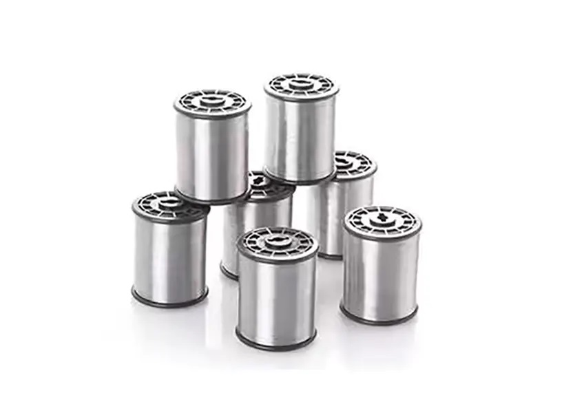
Aluminum MIG Wire: What Do You Need to Change?
Equipment set up for steel Aluminum MIG Wire cannot handle successfully without several deliberate changes. The wire feeding path is frequently a primary source of issues; therefore, addressing this area can resolve many common problems encountered when transitioning between materials.
The essential adjustments are:
- Change steel liners to ones made of PTFE or nylon. These low-friction materials let the soft Wire slide easily and stop the scraping that produces Aluminum shavings and eventual clogs inside the torch liner.
- Move to a spool gun or a push-pull Wire feeder. With a spool gun the entire Wire spool sits right on the torch body, so there is no long conduit for the Wire to kink or bird-nest in. A push-pull feeder adds a second set of drive rolls near the torch to pull the Wire steadily and keep it from being crushed along the way.
- Install U-groove drive rolls or knurled rolls specifically designed for Aluminum and other soft Wires. Ordinary V-groove rolls made for steel will squash Aluminum Wire even when tension is set reasonably low. Back off the drive roll pressure until it is just enough to push Wire without slipping.
- Keep polarity set to DCEP (direct current electrode positive). This setting is standard for Aluminum MIG Wire because it helps the arc break up and clean away surface oxides effectively.
- Choose pure argon or an argon-rich shielding gas. Argon gives the strong arc cleaning action Aluminum needs and keeps the arc quiet and stable. Shielding gases that include significant CO2, which work fine on steel, cause problems with Aluminum.
Spray transfer is the transfer mode used for the majority of Aluminum MIG Wire. Once you reach the right combination of voltage and Wire feed speed, the arc creates a steady, fine mist of droplets that produces an even, attractive bead. Pulsed spray offers another choice, especially helpful on thinner stock or anywhere you want stricter control over heat input, because metal only crosses the arc during the short high-current pulses instead of flowing all the time.
On Aluminum, a well-run MIG bead usually has a clean, shiny surface, a mild convex shape, and nicely tapered toes. If the bead or the surrounding area looks dull gray or sooty, poor gas coverage or some form of contamination is almost always the cause. Surface porosity that you can see typically comes from trapped moisture, leftover surface dirt, or gas flow that is too low.
TIG Technique for Aluminum: Does Precision Come at a Cost?
TIG Welding offers far greater command over heat, puddle shape, and exactly where filler goes compared to MIG, though it demands more hand-eye coordination and naturally takes longer to complete a joint. For thin Aluminum sheet, visible cosmetic welds, or applications where final bead appearance is a consideration, TIG is commonly selected.
Key points about TIG on Aluminum:
- The tungsten electrode stays solid and does not become part of the weld metal. You add filler rod manually, either in a steady stream or in quick dabs that match what the puddle is doing. Coordinating rod feed with torch angle and pedal control takes time and practice to feel natural.
- AC current is the standard choice rather than DC. During the electrode-positive portion of the cycle the arc scrubs away the oxide layer on the surface; the electrode-negative portion supplies the concentrated heat that actually melts and fuses the metal.
- How you prepare the tungsten makes a difference. For AC work on Aluminum you want a clean electrode with a rounded, slightly balled end. Sharpening it to a fine point the way you MIGht for DC steel Welding causes the tip to melt and degrade quickly.
- Using a gas lens and the right cup size helps keep the shielding gas smooth and steady. A gas lens creates a more even, less turbulent flow that protects wider beads and tricky joint shapes better than a standard collet body.
Filler rod for Aluminum TIG Wire needs to go in at a steady pace that keeps up with how fast you move the puddle. Adding rod too quickly builds up excess metal on top without good penetration underneath. Going too slow leaves a skinny bead with undercut along the edges. Observing the forward edge of the weld puddle, rather than focusing directly on the arc, provides a reliable signal for when to add filler metal.
Preparation of the surface before TIG is more demanding than for MIG. Mechanically remove the oxide layer using a stainless steel brush reserved exclusively for aluminum, and pre-clean the area with a solvent to prevent contaminants from being embedded in the material.
Matching Filler Alloy to Base Metal: A Practical Reference
Selecting an appropriate filler metal is a deliberate process. Common base alloys typically pair with a limited number of specific filler metals; an incorrect choice can result in a weld that appears sound initially but later experiences failure due to cracking, reduced strength, or inadequate corrosion resistance. The table below lists frequently encountered base alloys in general fabrication along with their typical matching fillers.
| Base Alloy | Recommended Filler | Process Suitability | Notes |
|---|---|---|---|
| 3003 | ER4043 or ER4047 | MIG and TIG | Good general-purpose option; smooth flow on thin sheet |
| 5052 | ER5356 | MIG and TIG | Helps retain corrosion resistance in marine environments |
| 6061 | ER4043 or ER5356 | MIG and TIG | ER4043 improves crack resistance; ER5356 provides higher strength |
| 6063 | ER4043 | TIG preferred | Produces clean visual results; widely used in architectural applications |
| 5083 | ER5183 or ER5356 | MIG and TIG | Preserves alloy strength; common in marine and cryogenic uses |
When you are unsure, check the compatibility tables put out by the filler metal supplier. Those guides give precise recommendations based on the actual chemistry of the base material instead of broad rules of thumb.
Common Mistakes That Compromise Aluminum Welds
The majority of problems and failed Aluminum welds come down to the same handful of avoidable mistakes. Spotting these early saves time, material, and rework.
- Inadequate oxide removal leaves residual film that can disrupt fusion and often contributes to porosity. Always start with a dedicated Aluminum-only stainless brush followed by solvent cleaning.
- Using the wrong filler alloy: A filler that does not match the base alloy can cause hot cracking in the heat-affected zone, reduced strength, or a bad appearance after anodizing. Identify the base alloy first.
- Incorrect drive roll pressure: Excessive pressure flattens soft Aluminum Wire and generates shavings that jam the liner. Too little pressure lets the Wire slip and feed unevenly. Find the sweet spot where Wire moves smoothly without being deformed.
- Inconsistent gas coverage: Drafts, loose hose connections, or low flow let air reach the puddle and oxidize the weld. Inspect fittings regularly and block ind from the work area.
- Ignoring heat buildup on multi-pass welds: Aluminum holds heat longer than steel, so each new pass adds more temperature. Give enough cooling time between passes or use a heat sink or backing to prevent burn-through and distortion.
- Contaminated filler rod: Skin oils and moisture from handling transfer easily to the rod surface. Wear clean gloves and keep rods stored in sealed containers to stay dry.
- Wrong tungsten type for AC TIG: Pure tungsten or zirconia-doped electrodes handle AC well on Aluminum. Thoriated tungsten is meant for DC work and breaks down or behaves poorly under AC.
- Inadequate joint fitup: Excessive gaps make it hard for Aluminum filler to bridge the joint completely, especially at the root. Aluminum does not fill wide openings as forgivingly as some steel procwesses do.
Two Practical Case Walkthroughs
Case A: MIG Weld on a Structural Aluminum Frame Section
The base material is 6061-series plate, roughly three-sixteenths inch thick. The joint is a fillet at a T-connection in a lightweight structural frame.
- Wipe both pieces down with acetone to clear away grease and dirt, then scrub along the weld path using a stainless brush reserved for Aluminum only.
- Choose ER4043 filler Wire because it pairs well with 6061 and offers solid resistance to cracking in the heat-affected area.
- Install a spool gun fitted with a PTFE liner, and adjust the drive roll tension to the lightest setting that still delivers steady Wire without flattening it.
- Use straight argon shielding gas and double-check the flow at the nozzle before starting the arc.
- Hold a slight push angle with the torch and keep travel speed steady to produce an even bead shape. If the bead edges do not wet out smoothly, tweak the voltage slightly.
- Once the weld has cooled, look it over carefully for any porosity, undercut, or uneven fusion at the toes before the piece moves on.
Case B: TIG Weld on Thin Aluminum Sheet for a Visible Seam
The base material is 5052-series sheet, about one-sixteenth inch thick. The joint is a butt weld that will stay exposed in the final product.
- Thoroughly degrease the edges and brush them clean. On material this thin, any leftover contaminant will stand out right away in a TIG bead.
- Pick Aluminum Welding Wire ER5356 TIG rod to maintain the good corrosion resistance that 5052 is known for.
- Dial the machine to AC and set a balanced wave—or lean slightly toward extra cleaning action—to handle the oxide along the narrow joint.
- Fit the torch with a gas lens and a larger cup size to create smooth, even gas coverage over the thin sheet.
- Add filler rod in short, deliberate dips that match the puddle's forward movement. Ease off the foot pedal near the end of the joint as heat builds up in the material.
- Check the completed bead for uniform crown height, smooth blending at the toes, and no signs of dull or darkened areas that suggest oxidation took place.
Shop Maintenance and Consumable Care
How well consumables are looked after has a direct impact on Aluminum weld quality. A limited set of routine practices can help address many common issues.
- Examine liners periodically and replace them when needed. Over time, accumulated Aluminum particles inside the liner can cause intermittent feeding, a condition that may be difficult to identify without removing the liner for inspection.
- Keep Wire spools sealed in bags with desiccant packets whenever they are not mounted. Moisture that reaches the Wire surface invites porosity and often requires extra gas purging to clear before reliable feeding returns.
- Wipe contact tips clean on a regular basis and swap them out before they wear enough to make the arc wander. Aluminum leaves buildup inside the tip that TIGhtens the opening and raises electrical resistance.
- Inspect gas hoses and torch connections at the beginning of every shift. Even a small leak creates the same effect as a nearly empty tank: spotty shielding and oxidized weld surfaces.
- Reserve brushes strictly for Aluminum and mark them so they never get used on steel or other metals. Cross-contamination from iron particles appears as dark specks or inclusions in the finished weld.
Closing: How to Frame Your Setup Decision
Deciding between Aluminum TIG Wire and Aluminum MIG Wire does not come down to one method being better overall. The suitability of each option depends on the specific combination of material thickness, production volume, joint design, and required bead appearance. MIG paired with a spool gun moves filler quickly on heavier sections and works efficiently in higher-production settings. Aluminum TIG Wire provides precise heat management on thin stock and delivers smoother, more attractive beads when looks are part of the requirement.
Filler selection follows straightforward reasoning: match the Wire chemistry to the base alloy and the conditions the joint will face in use. Wire delivery method, surface cleaning, and shielding gas setup are not minor details—they carry the same weight as the filler choice. A welder who pays steady attention to cleanliness, consumable upkeep, and proper process adjustments usually finds that Aluminum becomes far more manageable than its reputation implies. Most difficulties people run into stem from rushed preparation rather than anything unique to the material itself. Developing consistent habits in these areas brings reliable results on every weld, no matter the alloy or the process.
NEXT:Importance of Welding Wire Quality: How It Impacts Welding


