
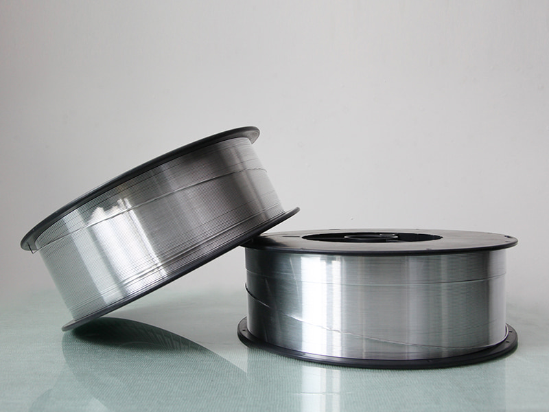
Why do we need aluminum welding wire
Article Directory
- 1 What Aluminum Welding Wire Is and When You Need It
- 2 Which Filler Wire Should I Use for My Base Alloy?
- 3 Do I Need a Spool Gun or Can I Run Aluminum Through My Standard MIG Setup?
- 4 What Shielding Gas Do I Need: Argon or Helium?
- 5 How Do I Avoid Common Defects?
- 6 Why Aluminum Requires Dedicated Filler Wire
- 7 Common Aluminum Filler Wires: Composition and Selection Guide
- 8 Practical Purchasing Considerations
- 9 Welding Processes for Aluminum: MIG vs TIG Selection
- 10 Shielding Gas Selection and Parameters
- 11 Equipment Configuration and Wire Feed Management
- 12 Welding Technique and Joint Preparation
- 13 Common Defects and Troubleshooting Methods
- 14 Practical Applications and Alloy Matching
- 15 Sourcing, Storage, and Handling Practices
- 16 Summary Guidance and Quick Reference
When metalworkers transition from steel to aluminum fabrication, they quickly encounter challenges that demand different approaches and materials. Working with lightweight alloys requires understanding why dedicated Aluminum Welding Wire becomes necessary, and manufacturers like Kunli Aluminum Welding Wire Manufacturers provide specialized solutions for these distinct requirements. The fundamental differences between ferrous and non-ferrous metals create unique welding scenarios that standard steel consumables cannot address.
What Aluminum Welding Wire Is and When You Need It
Aluminum filler wire is the added material that melts and combines with the base aluminum during fusion welding processes such as MIG and TIG to create a metallurgically sound joint. It must be produced specifically for aluminum because of the metal's quick-forming oxide skin, extremely high heat conduction, different rate of thermal expansion compared with steel or other metals, and distinctive way it solidifies—none of which match the behavior of steel welding consumables.
Common Misconception Alert: Wires labeled ER70S-6 or electrodes marked E7018 belong exclusively to steel welding and are never suitable for aluminum. Their melting ranges, chemical makeup, and mechanical characteristics are so different that attempting to use them on aluminum results in weak bonds, extensive cracking, or total weld failure.
| Problem | Why It Occurs with Aluminum | Quick Fix |
|---|---|---|
| Wire feeding difficulties | Soft wire deforms inside liner | Use spool gun or Teflon liner |
| Porosity in weld | Hydrogen from moisture or contamination | Clean base metal, check shielding gas purity |
| Hot cracking | Solidification stress in some alloys | Use ER4043 (silicon filler) |
| Lack of penetration | High thermal conductivity draws heat away | Increase amperage or add helium to argon |
Which Filler Wire Should I Use for My Base Alloy?
Selecting the correct filler wire depends primarily on the alloy series of the base metal you are joining:
5xxx series (magnesium-containing, non-heat-treatable): ER5356 is a common selection; it corresponds well to the base metal strength and offers suitable corrosion resistance in environments involving moisture, salt, or chemicals.
6xxx series (magnesium- and silicon-containing, heat-treatable): ER4043 is commonly chosen as it helps reduce the tendency for cracking during weld solidification while providing adequate strength in the completed joint.
2xxx series (copper-containing, heat-treatable): ER2319 is generally used when increased strength is a primary concern, such as with alloys like 2219. ER4043 can serve as an alternative for less demanding applications where minimizing cracking is prioritized over achieving higher strength.
1xxx series (essentially pure aluminum): ER1100 is selected for applications where closer color match, electrical conductivity, or corrosion performance are considerations. ER4043 provides a versatile option when smoother bead appearance and lower cracking risk are more relevant.
The AWS "ER" prefix means the wire is suitable for use as an electrode in MIG welding or as a filler rod in TIG welding. The numbers after "ER" identify the main alloy group and give a general indication of the strength you can expect from the deposited weld metal.
Do I Need a Spool Gun or Can I Run Aluminum Through My Standard MIG Setup?
Because aluminum wire is much softer than steel wire, it tends to buckle, kink, or feed unevenly in ordinary push-style MIG feeders built for harder materials.
Spool gun advantages:
- The wire travels only a very short distance from the spool to the contact tip, almost completely eliminating kinking and friction-related feeding issues.
- No long conduit is required, so feeding problems disappear.
- Small spools attach right to the torch, making the setup simple and portable.
Push-pull system benefits:
- Offers much longer reach from the wire feeder to the welding torch than a spool gun allows.
- One motor pushes from the feeder while a second pulls at the torch, keeping the wire straight and moving at a steady speed.
- Supports faster wire feed rates and higher deposition needed for production or thicker material.
A standard push-only MIG setup can handle aluminum wire successfully when:
- The distance from feeder to torch is kept fairly short.
- A low-friction Teflon or nylon liner is installed in place of a steel liner.
- U-groove drive rolls are used so the soft wire is not flattened or deformed.
- Drive-roll tension is adjusted carefully—too much pressure crushes the wire, too little lets it slip.
- Smaller-diameter aluminum wires need especially gentle treatment and precise alignment to feed smoothly.
What Shielding Gas Do I Need: Argon or Helium?
Pure argon is a common shielding gas used for Aluminum Welding. It gives a smooth, controllable arc, good oxide cleaning action around the weld pool, attractive bead shape, and enough penetration for thinner pieces.
Adding helium or switching to pure helium provides important advantages in certain cases:
- Much higher heat input, which helps keep a molten pool on thick sections or materials that conduct heat very rapidly.
- Faster possible travel speeds when you need to increase productivity.
- Greater penetration depth for achieving full fusion in groove joints.
- Higher arc voltage needed to keep the arc steady.
Pure argon provides a practical balance of performance and cost for general welding, repair, and light-to-medium fabrication tasks. In heavy fabrication or high-production shops welding thicker material, argon-helium mixtures (with helium percentage chosen for the job) frequently improve travel speed and penetration enough to make the extra gas expense worthwhile.
How Do I Avoid Common Defects?
Porosity prevention:
- Clean all base metal surfaces carefully with acetone or another approved cleaner to remove oils, grease, and shop contaminants.
- Use a stainless-steel brush kept only for aluminum to scrub off the oxide layer just before starting the arc.
- Store filler wire in a dry location and reseal opened spools or place them in a dry cabinet.
- Make sure the shielding gas is high-purity and adjust the flow rate to provide complete coverage without creating turbulence.
Cracking resistance:
- Choose fillers that contain silicon, such as ER4043 or ER4047, for base alloys that are sensitive to hot cracking.
- Reduce restraint in the joint by tacking in a balanced pattern and allowing some natural contraction as the weld cools.
- Keep heat input moderate to shorten the time the weld metal spends in the weak semi-solid condition.
- Use joint designs that help distribute shrinkage stresses more evenly, such as beveled preparations on heavier sections.
Feed problem solutions:
- Change out feed liners on a regular schedule, particularly when welding aluminum frequently.
- Clean drive rolls and guide tubes often to remove any accumulated aluminum particles.
- Select contact tips with bore diameters matched closely to the wire size.
- Adjust drive-roll pressure to a level that provides consistent wire delivery while avoiding slippage or crushing.
Why Aluminum Requires Dedicated Filler Wire
Thermal Conductivity and Heat Management
Aluminum pulls heat away from the weld area far more quickly than steel does. Even though pure aluminum melts at a lower temperature, this rapid heat loss makes it challenging to create and hold a stable molten pool. Welders therefore have to increase amperage, slow travel speed in some cases, or preheat the part to overcome the cooling effect and get proper fusion.
Aluminum Oxide Layer Formation
Aluminum immediately develops a hard oxide coating when exposed to air; this layer melts at a temperature much higher than the base metal and acts as a barrier to good wetting and fusion. Some filler wires assist in dealing with the oxide—silicon in ER4043 increases the pool's fluidity and helps disrupt the oxide film, while magnesium in ER5356 changes how the oxide interacts—but thorough cleaning of the base metal and wire surface before welding is still required no matter which filler you select.
Hydrogen Solubility and Porosity Risk
When molten, aluminum absorbs hydrogen very easily from sources such as surface moisture, lubricants, or humid shop air. As the weld pool solidifies, the metal can hold far less hydrogen, so the excess comes out of solution and forms round gas pores. Aluminum filler wires are manufactured with tight controls to keep hydrogen low—dry production areas, sealed packaging, and careful chemistry management—but correct storage and preparation remain essential to stop porosity from appearing in the finished weld.
Solidification Cracking Susceptibility
A number of aluminum alloys pass through a fairly wide temperature range in the semi-solid state during freezing; in that condition the metal has little strength and cannot resist the tensile stresses caused by shrinkage, which leads to hot cracking. Silicon-containing fillers such as ER4043 and ER4047 help address this by narrowing the solidification range. This promotes better feeding of liquid metal into areas of shrinkage, reduces susceptibility to stress-related issues, and yields a refined grain structure that inhibits crack formation and propagation.
Common Aluminum Filler Wires: Composition and Selection Guide
ER4043: Silicon-Bearing General Purpose Wire
Mostly aluminum with enough silicon to keep cracks at bay in heat-treatable alloys, yet the weld stays plenty strong for everyday jobs.
Advantages:
- Cuts down hot cracking when you're welding stuff that needs heat treatment.
- Flows nicely, leaving a clean-looking bead.
- Melts a bit easier, which helps you control the puddle.
- Turns a neutral gray after anodizing, so it blends with some base metals.
Typical applications:
- Bicycle frames and car parts.
- Architectural extrusions.
- General work on the usual heat-treatable alloys.
ER5356: Magnesium-Bearing High Strength Wire
Aluminum loaded with magnesium and a dash of manganese; matches the toughness and salt-water resistance of marine-grade stock.
Advantages:
- Gives you higher tensile strength right out of the arc.
- Stands up well in marine settings.
- Keeps its strength without extra heat treatment.
- Colors reasonably close to some base alloys after anodizing.
Considerations:
- IMore prone to cracking if you pair it with heat-treatable series.
- Stiffer, so it can snag in the drive rolls.
- Throws a little spatter unless you dial the machine in.
Common applications:
- Boats and offshore rigs.
- Tanks and pressure vessels.
- Heavy equipment builds.
- Railcar assembly.
ER4047: High Silicon Brazing-Type Wire
Packs in extra silicon for a low-melt eutectic; basically a brazing alloy that can still fill a groove.
Specialized uses:
- Automotive heat exchangers.
- Radiator patches.
- Hybrid braze-weld jobs.
- Dissimilar alloys where you don't want to melt the base.
The high silicon leaves a dark charcoal finish after anodizing—fine if looks don't matter, otherwise skip it.
ER1100: Commercially Pure Aluminum Wire
Almost straight aluminum with traces of iron and silicon; purity is the selling point, strength isn't.
- Application scope:
- Welding pure aluminum bases.
- Food-processing gear.
- Chemical plant parts that can't tolerate impurities.
- Fixing electrical conductors.
Mechanical strength remains lower than alloyed wires, limiting structural applications.
ER2319: High Strength Aerospace Wire
Copper-rich with magnesium, manganese, and friends; welds up to match copper-bearing aerospace alloys.
Characteristics:
- Hits high tensile numbers once you heat-treat the joint.
- Needs that post-weld bake to realize full properties.
- Cracks easily if your technique slips.
- Costs more than garden-variety fillers.
Practical Purchasing Considerations
Filler Selection Decision Matrix
| Base Alloy Family | Primary Filler Choice | Alternative Filler | Key Consideration |
|---|---|---|---|
| 1xxx (pure Al) | ER1100 | ER4043 | Purity requirements |
| 2xxx (Al-Cu) | ER2319 | ER4043 | Strength vs crack resistance |
| 3xxx (Al-Mn) | ER4043 | ER5356 | Formability needs |
| 5xxx (Al-Mg) | ER5356 | ER5183 | Corrosion environment |
| 6xxx (Al-Mg-Si) | ER4043 | ER5356 | Cracking tendency |
| 7xxx (Al-Zn) | ER5356 | Special alloys | Critical applications |
Practical Purchasing Considerations
Pick wire diameter to match the job: thin for light sheets and precision, thick for production and fat sections. Spool sizes run from mini-spools for the occasional fix to big reels that keep the welder fed all shift; just make sure you store the big ones right.
Welding Processes for Aluminum: MIG vs TIG Selection
Gas Tungsten Arc Welding (TIG/GTAW) Characteristics
TIG welding allows for precise heat control, making it suitable for thin material or applications where careful deposition is required.
Process advantages:
- Clean welds, almost no spatter.
- Exact heat control.
- Handles thin material without blow-through.
- Leaves joints that look finished straight off the torch.
Process limitations:
- Deposits metal slower than MIG.
- Takes real skill.
- Tungsten can contaminate if you touch the puddle.
- Not quick enough for production runs.
Typical TIG applications: include aerospace parts, food-processing equipment, and architectural pieces where appearance matters.
Gas Metal Arc Welding (MIG/GMAW) Characteristics
MIG pushes metal fast, ideal for thicker plates and shop floors.
Process advantages:
- Quick travel speeds.
- High deposition rates.
- Easier to train new hands.
- Eats through thicker material without drama.
Process limitations:
- Spatters more than TIG.
- Heat control is coarser.
- Needs spool guns or push-pull setups for aluminum.
- Soft wire likes to bird-nest if the feeder fights it.
Production panel welding, structural fabrication, and repair work benefit from MIG efficiency.
Alternative Joining Methods
- Friction stir welding joins without melting—great for aerospace.
- Resistance spot welding works for car bodies.
- Laser welding zips along on thin sheets in automated lines.
- Brazing with aluminum-silicon fillers lets you join without risking the base metal.
Process Selection Workflow Examples
Small repair scenario:
- BBase metal: Heat-treatable sheet, thin gauge.
- Process selection: TIG welding.
- Filler wire: ER4043, appropriate diameter.
- Shielding gas: Pure argon.
- Expected outcome: Clean cosmetic repair.
Production panel scenario:
- Base metal: Marine-grade sheet, medium thickness.
- Process selection: MIG with spool gun.
- Filler wire: ER5356, suitable diameter.
- Shielding gas: Argon or argon-helium blend.
- Expected outcome: Rapid joining with acceptable appearance.
Shielding Gas Selection and Parameters
Why Pure Argon Serves Most Applications
Argon arcs steady, starts easy, and keeps air out for a reasonable price. It's monatomic, so it ionizes without fuss, giving you smooth transfer and decent penetration on thin-to-medium stock.
When Helium Additions Improve Performance
Helium jacks up the arc voltage and dumps more heat into the weld. Mix it with argon or run it pure when:
Thickness considerations: Thinner stuff stays happy on straight argon; thicker plates welcome helium percentages that climb with the gauge.
Travel speed requirements:
- Production runs offset the helium price with faster passes.
- Lets you travel quicker without losing penetration.
- Higher deposition rates help pay for the extra gas.
Trade-offs:
- Helium costs more than argon.
- Arc starts get trickier.
- Being lighter than air, it needs higher flow to stay put.
- Too much helium can make spatter worse.
Gas Flow Rates and Delivery
Most Aluminum Welding runs fine with standard flow rates. Too much gas just burns money without better coverage, while too little lets air sneak in and ruin the weld with porosity or oxides.
Nozzle size matters—bigger wire needs a bigger nozzle to keep the shielding blanket wide enough around the arc.
Argon has to stay really clean; even small amounts of water vapor or oxygen will leave porosity and ugly oxide spots in the bead.
Practical Gas Selection Guidelines
| Material Thickness | Recommended Gas | Application Note |
|---|---|---|
| Thin sections | Pure argon | Cost-effective approach |
| Medium sections | Argon or argon-helium blend | Balance of cost and performance |
| Thick sections | Higher helium content | Improved penetration |
| Very thick sections | High helium or pure helium | Maximum heat input needed |
Equipment Configuration and Wire Feed Management
Spool Gun vs Push-Pull vs Direct Drive
Spool gun systems:
The spool sits right on the torch handle, so the wire barely travels before it hits the arc—almost no chance of kinks or tangles. Downside is the extra weight tires your arm out faster, and you swap small spools pretty often.
Push-pull systems:
Drive motors work together—one pushes from the feeder, the other pulls at the torch. That combo stops the wire from buckling in the liner and lets you reach farther with steady feeding. Costs more up front, but pays off when you're running a lot of aluminum.
Direct drive systems:
Plain push-feed setup from the feeder works okay for short runs if everything's tuned right. You need the correct liner, good drive rolls, and just the right tension. This represents a cost-effective approach for workshops that primarily work with steel but occasionally handle aluminum.
Liner Selection and Maintenance
Steel liners chew up soft aluminum wire with too much drag and shave little curls into the path. Switch to Teflon or nylon liners—they slide the wire smoothly and keep things clean.
Replace liners on a schedule:
- Heavy production—change them regularly.
- Light or occasional use—stretch the intervals.
- Swap immediately the moment feeding starts acting squirrelly.
Install liners the right way: cut them exactly to length, deburr the ends, route them straight without sharp bends, and lock them down securely at both the feeder and torch.
Drive Roll Configuration
Use U-groove or knurled rolls made for aluminum—they cradle the wire without flattening it. Steel V-groove rolls mash aluminum wire flat, cause feeding jams, and leave bits of crushed metal that mess up the weld.
Set drive roll pressure carefully:
- Begin with almost no squeeze.
- Bump it up slowly until the wire feeds without slipping.
- Never crank it so hard you see flat spots or deformation.
Too little pressure lets the wire slip and speed jumps around; too much mashes the wire and clogs the contact tip.
Contact Tip Sizing and Replacement
Aluminum contact tips need a slightly bigger bore than steel tips for the same wire size—enough clearance to avoid binding, but not so much that you lose good electrical contact.
Too much slop means poor current pickup and extra spatter; too tight and the wire sticks or burns back.
Tips wear faster at high amps and long duty cycles—production jobs eat them quickly, while hobby or repair work makes them last much longer.
Feed System Setup Checklist
- Make sure the liner is Teflon or nylon (aluminum-friendly).
- Confirm U-groove drive rolls are in place.
- Set drive roll pressure to a level sufficient for reliable wire feeding.
- Verify contact tip bore matches the wire diameter with proper clearance.
- Look over the whole wire path for kinks, sharp turns, or damage.
- Check that the spool spins freely without drag.
- Clean drive rolls and liner interior.
- Run a test feed across the expected amperage range to confirm steady delivery.
Welding Technique and Joint Preparation
Surface prep makes or breaks aluminum welds—the oxide skin and any grease or dirt left behind cause porosity and weak fusion if you skip it.
Cleaning Sequence
Begin by degreasing the surface: Wipe it with acetone, isopropyl alcohol, or a dedicated solvent to remove oils and fingerprints. Use lint-free cloths to avoid transferring fibers, and allow the area to dry thoroughly before proceeding.
Mechanical oxide removal: grab a stainless steel brush kept only for aluminum (never cross-contaminate with steel). Brush in the direction of travel to avoid forcing contaminants into the joint. Perform this cleaning immediately before initiating the arc.
Chemical alternatives: alkaline cleaners or acid etches strip oxide i'production settings. Rinse thoroughly and dry completely so no chemicals stay behind to cause trouble.
Joint Design by Thickness Range
Thin materials:
- Straight butt joints, no bevel needed.
- Keep root gaps tiny.
- Use plenty of tack welds to fight distortion.
Medium thickness:
- Bevel the edges with a good included angle.
- Set a reasonable root gap for full penetration.
- Add backing strips when you can only weld from one side.
Heavy sections:
- Double-bevel prep on thick plate.
- Build with multiple passes.
- Think about preheating to head off cracks.
Heat Control Strategies
Aluminum pulls heat away so fast you have to manage it differently than steel.
Back-step welding: break long welds into short sections and weld each one backward relative to the overall direction—lets heat settle before the next bit.
Stitch welding: drop short welds along the joint, then come back later to fill the spaces—spreads heat out over time and distance.
Heat sink techniques: clamp copper bars or chill plates under thin work to soak up extra heat. Water-cooled setups keep things even cooler when dimensions really matter.
Travel Speed and Arc Parameters
Move too fast and you risk lack of fusion; crawl too slow and you overheat, warp parts, or grow big grains.
Pick settings that balance:
- Thickness sets the baseline heat you need.
- Joint type changes how heat flows away.
- Wire size controls how much filler goes in.
- Position (flat, horizontal, vertical, overhead) changes how you have to handle the torch.
Preheating Considerations
Thick pieces and crack-prone alloys often need preheat to the right range—check with temp sticks or an infrared gun. Too much heat hurts strength in heat-treatable stuff and just wastes energy.
Let welds cool naturally in calm air. Blowing compressed air or quenching with water can crack sensitive alloys or lock in bad stresses.
Common Defects and Troubleshooting Methods
Porosity: Causes and Solutions
Round gas pockets scattered through the weld metal usually come from hydrogen getting trapped as the puddle freezes.
Root causes:
- Oils, grease, moisture, or dirt left on the surface
- Shielding gas not covering the arc well enough
- Water picked up in the filler wire or soaked into the base metal
- High humidity in the shop air
Diagnostic steps:
- Look closely at how well the base was cleaned before welding
- Double-check gas purity and make sure flow is steady and adequate
- See how the filler wire has been stored—any signs of dampness?
- Pull the liner and check for dirt, shavings, or old residue inside
- Feel the shop humidity—anything over about 60% can start causing trouble
Corrective actions:
- Wipe and brush the joint area fresh right before you strike the arc
- Throw out any wire that feels damp or looks discolored
- Bump up the gas flow a notch to widen the shield
- Test the gas supply with a new bottle if you suspect contamination
- Keep wire sealed in dry storage or use a heated cabinet in muggy areas
- Stick to procedures that keep hydrogen low from start to finish
Hot Cracking and Solidification Issues
Cracks that run right down the middle of the weld bead point to solidification cracking while the metal freezes.
Contributing factors:
- Parts locked in tight fixtures that won't let the weld shrink freely
- Base alloy that's naturally prone to cracking
- Wrong filler picked for the job
- Too much heat dumped into the joint
- Joint design that piles stress in one spot
Solutions:
- Swap to ER4043 instead of ER5356 when cracking shows up
- Loosen up the clamping or use less rigid fixturing
- Dial back amps, voltage, or travel speed to cut total heat
- Modify the welding sequence by applying tacks first, then complete the fill using a pattern that distributes shrinkage.
- Open up the joint angle or add a slight root face for more forgiving solidification
Lack of Fusion and Penetration
Weld metal doesn't tie in properly to the base, leaving weak spots along the edges or at the root.
Underlying issues:
- Not enough heat for the thickness you're working
- Oxide layer still sitting between filler and base
- Traveling too fast for the arc to dig in
- Torch angle blocking good access to the joint
Remediation:
- IRaise current to get deeper penetration without overdoing it
- Mix in some helium to crank up the arc heat
- Be more aggressive with cleaning—oxide has to go completely
- Slow down just enough to let the puddle wet the sides
- Tweak the torch angle or bevel the edges so you can get straight in
Appearance Problems
Bead looks different depending on filler and settings. ER4043 usually gives a lighter gray that matches many heat-treatable bases after anodizing. ER5356 tends darker. ER4047 with all that silicon goes charcoal or near-black.
Excessive spatter indicates:
- Wrong gas mix or too little coverage
- Wire feed speed cranked too high
- Arc voltage pushed beyond the sweet spot
- Dirty or oily base metal
Rough bead surface suggests:
- Wire feeding in fits and starts
- Gas shield breaking down
- Filler wire picked up contamination along the way
- Wrong torch angle or work angle throwing the puddle off
Practical Applications and Alloy Matching
Marine Construction and Magnesium-Bearing Alloys
Saltwater can corrode aluminum rapidly without suitable material selection. Magnesium-based alloys often demonstrate improved resistance in such conditions, requiring careful compatibility assessment.
Recommended practice:
- Base metal: Anything rated marine-grade
- Filler: ER5356 or ER5183 for matching corrosion behavior
- Process: MIG when you need to cover ground quickly
- Shielding gas: Straight argon is commonly employed for welding tasks.
The weld stays strong without heat treatment afterward, and good filler choice keeps the whole structure fighting rust evenly.
Automotive and Structural Heat-Treatable Applications
Heat-treatable alloys give nice strength plus good forming—common in car frames, bike parts, and building exterctions.
Welding challenges:
- Tend to crack as they solidify
- Heat-affected zone drops strength noticeably
- Parts warp easily if heat isn't managed
Solutions:
- Reach for ER4043 to keep cracking way down
- Clamp or fixture everything solidly to fight distortion
- Plan for post-weld aging if you need to claw back some of the original strength
Repair vs New Fabrication Scenarios
Repair scenario: Cracked heat-treated bicycle frame
The frame already went through heat treatment, so welding heats it locally and softens those zones. ER4043 filler gives a decent repair for street riding or low-stress use. For serious racing or high loads, scrap the frame and start fresh.
New fabrication scenario: Marine aluminum boat hull
Starting clean lets you plan the weld sequence, clamp smart, and pick settings that minimize problems. Running ER5356 on MIG builds tough, saltwater-proof joints all over the hull with good production speed.
Sourcing, Storage, and Handling Practices
Wire quality starts at the mill and ends at your torch—keep it clean and dry or the welds suffer.
Specification Standards
AWS A5.10 spells out what Aluminum Welding rods and electrodes have to meet—chemistry limits, strength minimums, how they're made, everything.
Storage Requirements
Water turns into hydrogen porosity fast on aluminum wire. Protect it:
- Keep spools in sealed plastic tubs or bags
- Store in a dry room—lower humidity the better
- Get them up off the concrete on shelves or pallets
- Utilize existing inventory in chronological order of receipt.
- Check seals and packaging before opening anything
Once a spool's cracked open in a humid shop, slip it into a resealable bag with some desiccant packs to keep moisture out.
Supplier Selection Factors
Commodity applications:
- General shop work can live with standard specs
- Price usually wins out
- Local suppliers cut shipping costs and wait time
Critical applications:
- Aerospace or pressure vessels need certified lots
- Full traceability back to the heat
- Test reports showing exact chemistry
- You pay extra for that peace of mind
Summary Guidance and Quick Reference
Picking aluminum filler comes down to matching the base alloy, getting the strength you need, and making the process behave. ER4043 works great on heat-treatable stuff where cracking is the enemy. ER5356 steps up for magnesium alloys and anything facing saltwater.
| Base Alloy | Recommended Filler | Shielding Gas | Equipment Notes |
|---|---|---|---|
| Marine-grade alloys | ER5356 | Argon | Standard MIG setup |
| Heat-treatable alloys | ER4043 | Argon | Monitor for cracking |
| Copper-bearing alloys | ER2319 or ER4043 | Argon | Aerospace applications |
| Pure aluminum | ER4043 or ER1100 | Argon | Non-structural work |
Pre-Weld Setup Checklist
- Nail down the base alloy and pick a filler that plays nice with it
- Degrease, then brush with a stainless dedicated to aluminum
- Install the right liner and U-groove rolls for aluminum
- Match contact tip bore to wire size with a touch of clearance
- Set gas flow and prove the supply is clean
- Run a test feed to make sure wire comes out smooth before you start the real job
Understanding these fundamental principles enables reliable aluminum joining across diverse applications and production environments. Whether fabricating marine structures that demand corrosion resistance or repairing heat-treatable automotive components, the selection of appropriate filler wire directly influences weld quality and long-term performance. Metalworkers who master the relationship between base alloy chemistry, filler composition, and process parameters can confidently approach Aluminum Welding challenges while avoiding common pitfalls that compromise joint integrity.
Related Products
-
 View More
5154 Aluminum Alloy Welding Wire
-
 View More
ER4043 Silicon Aluminum Welding Wire
-
 View More
ER4047 Aluminum Mig Welding Wire
-
 View More
ER5154 Al-Mg Alloy Wire
-
 View More
ER5087 Magnesium Aluminum Welding Wire
-
 View More
Aluminum Welding Wire ER5183
-
 View More
Aluminum Welding Wire ER5356
-
 View More
ER5554 Aluminum Welding Wire
-
 View More
ER5556 Aluminum Welding Wire
-
 View More
ER1100 Aluminum Welding Wire
-
 View More
ER5754 Aluminum Welding Wire
-
 View More
ER2319 Aluminum Welding Wire