
Selecting Aluminum TIG Wire for Weld Consistency
Article Directory
- 1 What is Aluminum Tig Wire?
- 2 What is it about wire metallurgy that alters weld behavior?
- 3 How do production and form factor affect field performance?
- 4 Which common fillers are chosen and why?
- 5 How should shops think about the ER4043 vs. ER5356 choice?
- 6 What preparation steps reduce porosity and contamination risks?
- 7 What welding parameters should change depending on the wire?
- 8 Why do feeding methods matter for aluminum wire users?
- 9 How does wire chemistry interact with base metal choices in tricky joints?
- 10 What defect patterns point to wire-related root causes?
- 11 How should quality assurance and traceability be managed for consumables?
- 12 What role does wire play in additive applications and WAAM?
- 13 What are practical storage and handling rules to protect wire performance?
- 14 How do welding teams identify when to invest in premium wire features?
- 15 What inspection and testing link wire to weld acceptability?
- 16 What practical checks should appear on a welding checklist focused on the wire?
- 17 Where is wire technology likely to influence fabrication next?
Aluminum TIG welding demands precision at every stage—from joint preparation to final inspection. Central to this process is the filler wire: a consumable whose chemistry, consistency, and handling directly influence weld integrity, productivity, and compliance. While welders focus on technique and parameters, the source of the wire—the Aluminum TIG Wire Suppliers—plays a critical, often undervalued role. Suppliers do more than distribute spools; they ensure metallurgical accuracy, deliver traceable documentation, and provide application-specific guidance that bridges workshop practice and material science. In sectors like aerospace, automotive, or marine fabrication, where weld performance impacts safety and longevity, partnering with technically aligned suppliers becomes a foundational element of quality assurance.
What is Aluminum Tig Wire?
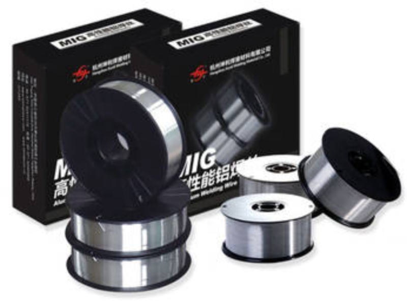
Aluminum Tig Wire is the filler metal used in TIG (tungsten inert gas) welding of aluminum. It's a purpose-made aluminum alloy wire that the welder adds into the molten arc pool to build the weld joint and restore material continuity. The wire's exact composition — small, controlled additions of elements like silicon, magnesium, manganese or others — determines how the weld metal flows, solidifies, and performs in service. In short, Aluminum Tig Wire is the controllable ingredient that links welding technique to the final mechanical and cosmetic performance of an aluminum joint.
What is it about wire metallurgy that alters weld behavior?
Aluminum Tig Wire is an engineered alloy rather than a generic metal stick. Alloying elements such as silicon and magnesium tune how the molten weld flows, how quickly it solidifies, and how the deposited metal ages or resists corrosion. Small trace elements and residual impurities can change the likelihood of porosity or the response to heat-treatment after welding. Because of this, selecting a wire is as much a materials decision as a procedural one: the composition determines how aggressive the weld pool is, how much dilution from the base metal is acceptable, and whether post-weld operations will be needed.
How do production and form factor affect field performance?
- Alloy chemistry control: Tight control of alloying elements and trace impurities affects melt behavior, solidification, and final weld metal properties; inconsistent chemistry can change fluidity, introduce porosity risk, or alter mechanical response.
- Microstructure from process route: Casting + drawing versus extrusion + drawing produce different grain structures and internal stresses; those differences influence wire ductility, spring-back, and how reliably a wire feeds and melts.
- Surface condition and cleanliness: Mill-scale, residual lubricants, drawing oils, or microscopic oxides on the wire surface raise the chance of contamination-related defects when the wire melts. Cleaner surfaces reduce the need for corrective rework.
- Diameter tolerance and roundness: Tight diameter control and consistent roundness reduce slippage, chatter, and erratic feed in both manual and automated feeders; loose tolerances increase drive-wheel wear and feeding interruptions.
- Heat treatment/softness balance: Annealing levels determine flexibility; wire that is too soft kinks or tangles, while wire that is too hard can fracture or damage liners and drive rollers. Proper thermal processing yields manageable stiffness for the intended feed method.
- Wire diameter selection: Diameter affects deposition rate, required current range, and access to tight joints; choosing an appropriate diameter affects heat input and bead profile during welding.
- Spool vs. straight lengths: Spooled wire suits mechanized and orbital systems; straight lengths are easier for manual bench work. Using the wrong format increases setup time and the risk of tangles or feed problems.
- Spool size and hub design: Large bulk spools reduce changeovers but can introduce greater inertia and require stronger brakes; small spools are easier to handle but increase frequency of spool swaps. Hub geometry and spool tension affect how smoothly wire pays off.
- Liner and feeder compatibility: Liner inner diameter, material, and condition interact with wire finish; mismatches produce drag, bird-nesting, or feeding hang-ups. Proper liner selection improves feed reliability.
- Packaging dryness and sealing: Spools shipped and stored with moisture control (sealed bags, desiccants) protect against hydrogen pickup and premature oxidation; poor packaging increases porosity risk once welding begins.
- Leader/heel preparation and spooling technique: How the wire end is secured and the spool wound impacts initial feed behavior; poorly wound spools can snag, causing downtime and inconsistent arcs.
Which common fillers are chosen and why?
A practical comparison table helps welders decide at a glance.
| Property to balance | Wire type commonly used | Why it matters |
|---|---|---|
| Fluidity during melting | Al-Si alloy wire | Higher silicon improves flow into tight cast surfaces |
| Deposited strength after cooling | Al-Mg alloy wire | Magnesium increases strength in many wrought alloys |
| Corrosion resistance in marine atmospheres | Al-Mg variant or special marine grade | Magnesium-bearing weld metal performs well against chlorides |
| Compatibility with heat-treatment cycles | Purpose-made wire for heat-treatable alloys | Some wires retain desired response after post-weld heating |
| Suitability for additive processes | Wire engineered for WAAM | Feedstock needs consistent chemistry and low contamination |
(Manufacturers often label fillers by composition groups; select based on how the property column matches the part’s in-service demands.)
How should shops think about the ER4043 vs. ER5356 choice?
When a joint calls for fluid filling into cast parts or for easy puddle control on aluminum extrusions, a silicon-bearing wire is often used because it reduces solidification cracking risk and helps the weld metal flow. Where deposited strength and strain resistance are priorities, magnesium-bearing wire is frequently preferred because it contributes to a tougher weld metal after solidification. The trade-off is that magnesium-rich fillers can be more sensitive to restraint and may need attention to travel speed and joint design. These are decisions about how the wire chemistry aligns with the base metal and the loading environment.
What preparation steps reduce porosity and contamination risks?
Hydrogen porosity is the ubiquitous enemy when welding aluminum. The weld pool readily absorbs hydrogen from moisture or oils when molten, and trapped hydrogen produces voids. Control measures include dry, clean wire storage; eliminating aqueous contaminants from joint preparation; and maintaining stable shielding gas flow. Practical approaches — sealed containers for spools, routine solvent cleaning of parent metal, and avoiding drafts in the welding area — reduce the hydrogen sources that create porosity. Industry guidance also emphasizes consistent feed and proper torch angles to avoid turbulence that can trap gas in the pool.
What welding parameters should change depending on the wire?
Shielding gas, current waveform, and heat input are all tuned around the chosen wire. Argon remains the standard shielding gas for GTAW, but adding a fraction of helium is a tool for deeper penetration or higher travel speeds on thicker sections. Alternating current balance, when used, is a dial that trades oxide cleaning action against penetration and bead shape; different wire chemistries respond differently to these settings. Amperage is selected to melt the wire and the base evenly without excessive dilution or burn-through; wire diameter narrows the acceptable current band, so diameter choice is as consequential as alloy selection.
Why do feeding methods matter for aluminum wire users?
Manual feeding offers tight, tactile control for thin sheets or detailed work, while automated or orbital feeding depends on consistent spool quality and diameter tolerance. Problems like kinking, bird-nesting, or inconsistent drive-roll grip often trace back to wire finish, spool tension, or liner condition. For orbital or automated TIG processes — increasingly used in high-volume or safety-critical applications — wire surface consistency and precise tolerances become essential to avoid interruptions and defects. Providers such as Kunliwelding supply spooled wire with controlled packaging aimed at automated feed systems, and shops find that small improvements in spooling and liner finish can cut downtime in automated cells.
How does wire chemistry interact with base metal choices in tricky joints?
Welding heat-treatable alloys or castings places constraints on filler selection. When a base material will be exposed to a strengthening heat-treatment after welding, the filler metal must be chosen so that the whole welded assembly meets the intended mechanical profile after that treatment. For cast alloys, higher fluidity wires tend to wet the rougher surfaces better and reduce trapped porosity. In joints where high-strength wrought alloys are present, filling with a magnesium-bearing wire may help preserve tensile performance. If a component will later be anodized, the visual match between weld and substrate can influence alloy choice because silicon and magnesium influence color and surface finish after anodizing.
When engineers see certain defect modes, wire is often implicated:
- Porosity scattered through the bead often points to moisture on wire or in the welding atmosphere.
- Longitudinal cracking during solidification suggests a mismatch between filler fluidity and the joint's solidification conditions.
- Inclusions and lack of fusion can point to oxide entrapment, dirty wire, or poor arc access that prevents proper metal transfer.
- Unexpected weld metal strength or ductility deficits often follow from excessive dilution with a weaker base metal or the wrong filler alloy choice.
Troubleshooting starts with habit checks: inspect wire packaging, confirm humidity control, and verify torch travel and gas coverage before assuming procedural faults.
How should quality assurance and traceability be managed for consumables?
Critical applications in aerospace, marine, or regulated equipment require that each spool carry documentation traceable to a mill cert that records chemical analysis and mechanical test results. Incoming inspection routines that verify diameter and surface condition, plus lot tracking so that deposited weld metal chemistry can be traced back if problems arise, are standard on higher-assurance production lines. Simple controls — FIFO rotation, dedicated dry storage, and routine visual checks on spools — reduce variability that affects welding outcomes.
What role does wire play in additive applications and WAAM?
Wire-arc additive processes rely on long, continuous feed with consistent chemistry and minimal contamination. Feedstock intended for such systems needs different handling and verification than shop-level filler wire: spooling that minimizes tangles, surface finishes that resist oxide pick-up, and chemistry tailored for layer-by-layer deposition are part of an integrated feedstock strategy.
What are practical storage and handling rules to protect wire performance?
Practical storage and handling rules are essential to preserve the performance of Aluminum Tig Wire and prevent defects such as porosity or feeding issues. The wire should always be stored in a clean, dry, and temperature-stable environment, away from moisture, oil, and dust. Unopened spools must remain sealed in their original packaging with desiccants to prevent hydrogen absorption and surface oxidation. Once opened, spools should be used promptly or kept in heated storage cabinets with humidity control.
Handling must be careful and consistent. Operators should wear clean gloves to avoid transferring grease or salts that can contaminate the wire surface. Spools must be lifted by their hubs, not the flanges, to prevent bending or damage. Any kinked or dented sections should be cut away before feeding to avoid erratic wire movement.
A First-In, First-Out (FIFO) inventory system ensures older wire is used before new deliveries, minimizing aging or corrosion risk. During production, wire feed equipment and liners should be regularly cleaned to remove debris and aluminum dust. Following these storage and handling guidelines helps maintain arc stability, reduce porosity, and ensure that each weld made with Aluminum Tig Wire meets consistent quality standards.
Premium wire characteristics can include tighter diameter tolerances, controlled low hydrogen content, and cleaner surface finishes. When a process steps from manual benchwork to automated or orbital welding, the cost of downtime and rework grows, making tighter consumable control economically sensible. Shops that adopt more automation also find value in packaging and spool features that reduce setup time and feed interruption. When evaluating a supplier or a wire grade, align the investment with the downstream cost of defects and with the required certification level for the finished assembly.
What inspection and testing link wire to weld acceptability?
1. Incoming Wire Inspection
- Visual examination: Check the wire surface for oxidation, scratches, oil residues, or mechanical damage that could transfer contaminants into the weld pool.
- Diameter and roundness check: Use micrometers or gauges to confirm that the wire meets specified tolerances for consistent feeding and current density.
- Spool condition: Inspect spooling tension, winding pattern, and end-tie integrity to avoid bird-nesting and feeding issues.
- Packaging and labeling review: Verify sealed packaging, desiccant presence, lot number, and mill certificate match the purchase order.
2. Chemical and Physical Verification
- Spectrochemical analysis: Sample test from each lot to confirm alloy composition matches the required filler classification (e.g., silicon or magnesium content).
- Mechanical sampling: Tensile or hardness checks on drawn wire strands can identify over-work or improper annealing that affects ductility and feed performance.
- Hydrogen content monitoring: Some critical applications use low-hydrogen wire verification to control porosity risks.
3. Welding Trial or Qualification Testing
- Test bead welding: Run a short weld under production parameters to observe puddle behavior, arc stability, and surface appearance; immediate visual cues often expose wire contamination.
- Procedure Qualification Record (PQR) welds: Produce test coupons using the wire and intended base metal, then evaluate mechanical and metallurgical results to confirm compatibility.
- Operator qualification coupons: Ensure the welder can achieve code-acceptable welds using that specific wire type and diameter.
4. Destructive Testing of Weld Metal
- Tensile tests: Measure weld-metal strength relative to base metal; deviations can indicate dilution or filler-metal mismatch.
- Bend tests: Reveal lack of fusion, inclusions, or internal cracks caused by improper wire composition or contamination.
- Fracture or macro-etch tests: Examine bead cross-sections to assess penetration, fusion line integrity, and porosity distribution.
- Chemical analysis of deposited metal: Confirms that filler contribution is within expected alloy limits after dilution with the base.
5. Non-Destructive Examination (NDE)
- Visual inspection (VT): Look for undercut, porosity, or cracking on weld surface.
- Dye-penetrant testing (PT): Detects surface-breaking cracks or inclusions associated with poor filler flow or contamination.
- Radiographic or ultrasonic testing (RT/UT): Identifies internal porosity, lack of fusion, or slag inclusions that may trace back to wire defects or handling errors.
- Macro-examination: Simple polish-and-etch methods to visualize bead shape and internal fusion boundaries.
What practical checks should appear on a welding checklist focused on the wire?
- Confirm spool lot documentation and mill cert match order.
- Verify spool surface is clean and free from corrosion or scale.
- Store and carry spools in sealed packaging until use.
- Run a test bead under production parameters and inspect for porosity or cracking.
- Record feeder tension and liner condition for automated setups.
Where is wire technology likely to influence fabrication next?
As industries demand lighter, more efficient assemblies, wire formulations that balance weldability and mechanical performance will be in demand. Wire designed for deposition-based fabrication methods and feedstock that accommodates additive thermal cycles will probably see wider use.
Choosing Aluminum TIG Wire Suppliers is not a simple transactional decision, but a technological collaboration. It's a technical partnership where the consistency of the wire's chemistry, the integrity of the packaging, and the support for rapid response determine the actual welding results. From humidity-controlled manufacturing to batch-specific certifications, reliable suppliers integrate quality into every stage, allowing manufacturers to focus on process optimization rather than defect troubleshooting. As aluminum welding technology evolves, new alloys emerge, automation processes advance, and increasingly stringent sustainability requirements arise, forward-thinking suppliers are continuously enhancing their capabilities: investing in cleaner production methods, specialized wire formulations, and digital traceability. For workshops committed to improving welding reliability, this collaborative model transforms welding wire from a commodity into a key element of success. By matching a supplier's capabilities to the specific needs of a project—whether it's an orbital TIG welding system or a high-purity aerospace application—teams not only obtain the necessary materials but also ensure predictable performance and long-term compliance.
NEXT:What Fuels Aluminum Braided Wire Demand
Related Products
-
 View More
5154 Aluminum Alloy Welding Wire
-
 View More
ER4043 Silicon Aluminum Welding Wire
-
 View More
ER4047 Aluminum Mig Welding Wire
-
 View More
ER5154 Al-Mg Alloy Wire
-
 View More
ER5087 Magnesium Aluminum Welding Wire
-
 View More
Aluminum Welding Wire ER5183
-
 View More
Aluminum Welding Wire ER5356
-
 View More
ER5554 Aluminum Welding Wire
-
 View More
ER5556 Aluminum Welding Wire
-
 View More
ER1100 Aluminum Welding Wire
-
 View More
ER5754 Aluminum Welding Wire
-
 View More
ER2319 Aluminum Welding Wire